Chapter 2.
PART NAMES AND FUNCTIONS
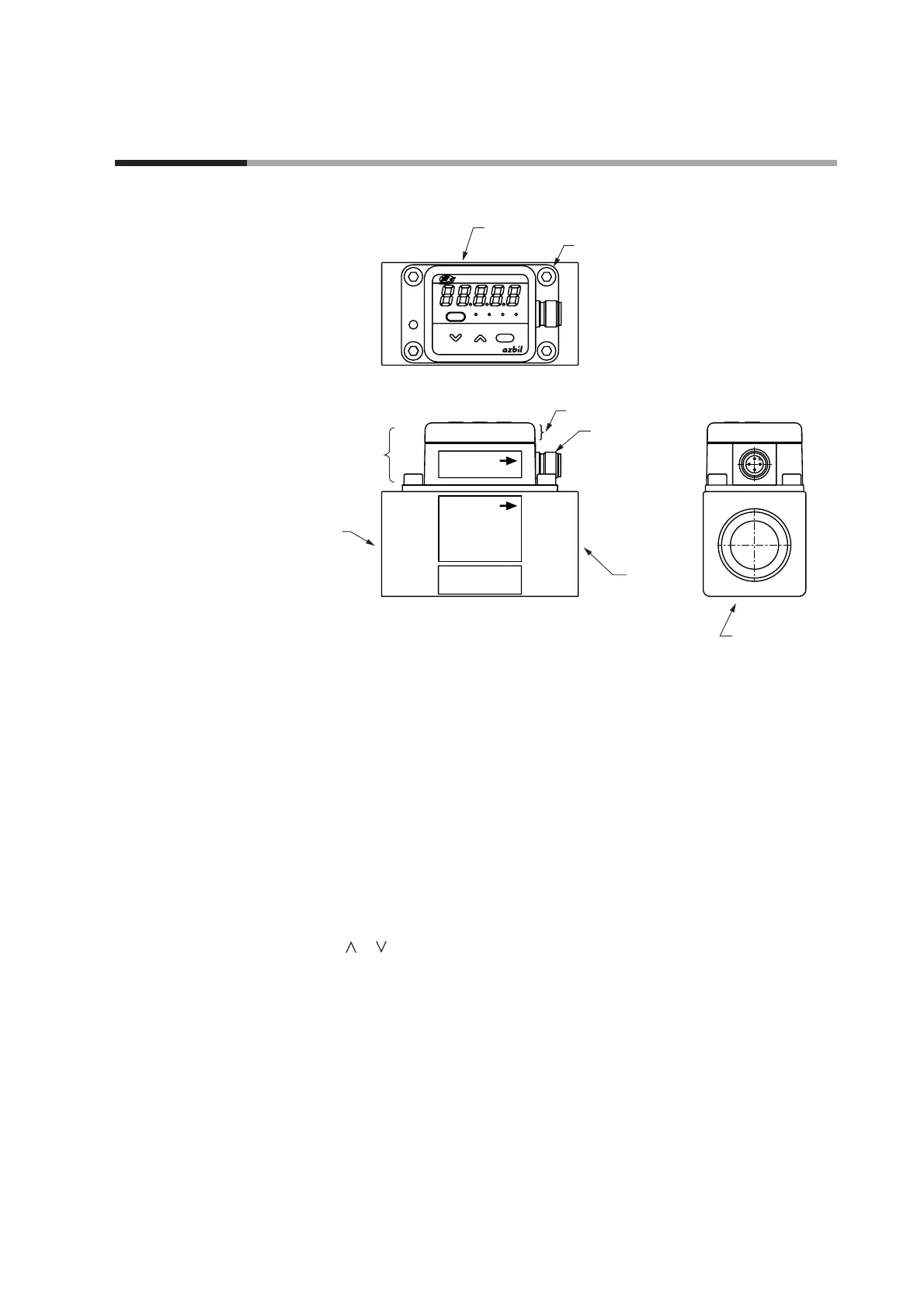
■ Parts name and functions
Flow rate display: This 7-segment LED indicates instantaneous flow rate or inte-
grated flow amount. For the integrated flow, the first 4 digits
and last 5 digits are displayed separately. The 7-segment dis-
play also indicates settings in setting mode and alarm codes
when an alarm occurs.
LED lamp:
[L/min] Lights up while instantaneous flow rate is indicated.
[L] Lights up while integrated flow is indicated.
[EV] Synchronized with event output
[AL] Lights up when an alarm occurs
Keys:
[mode] Changes the display or switches to setting mode, etc.
[][] Increases/decreases the value of a setting, changes the display
mode, etc.
[enter] Used to finalize function settings and parameter settings
Main flow path: Connects to pipes. Inlet and outlet are marked.
Measurement module
:Removable for maintenance. Can be changed with a new one
for the MCF0250, MCF0400 and MCF0500.
Display unit: Can be rotated in a plane parallel to the flow path. Rotates
180° clockwise and 90° counterclockwise, for viewing from
any direction.
Connector: Provides the power and signal connections.
Bolts: Fasten the measurement module in the main flow path.

 Loading...