13
Chapter 3. MOUNTING AND WIRING
■ Wiring
● Cautions for wiring
• Supply a power voltage within the specified range.
• Keep the MCF wiring (conduit) away from power wiring or high voltage wires.
•When connecting the connector, push the two parts together, and then tighten
the nut by hand to 0.4 to 0.6 N•
m. Improper tightening can damage the MCF, or
lead to a loss of the IP65 seal, or allow the connector to come loose due to vibra-
tion.
• Do not pull the cable forcibly, and do not lift the MCF by the cable (pull-out
strength 40 N max., bending force 20 N max.) Do not bend the cable repetitively
or put a constant pulling stress on it.
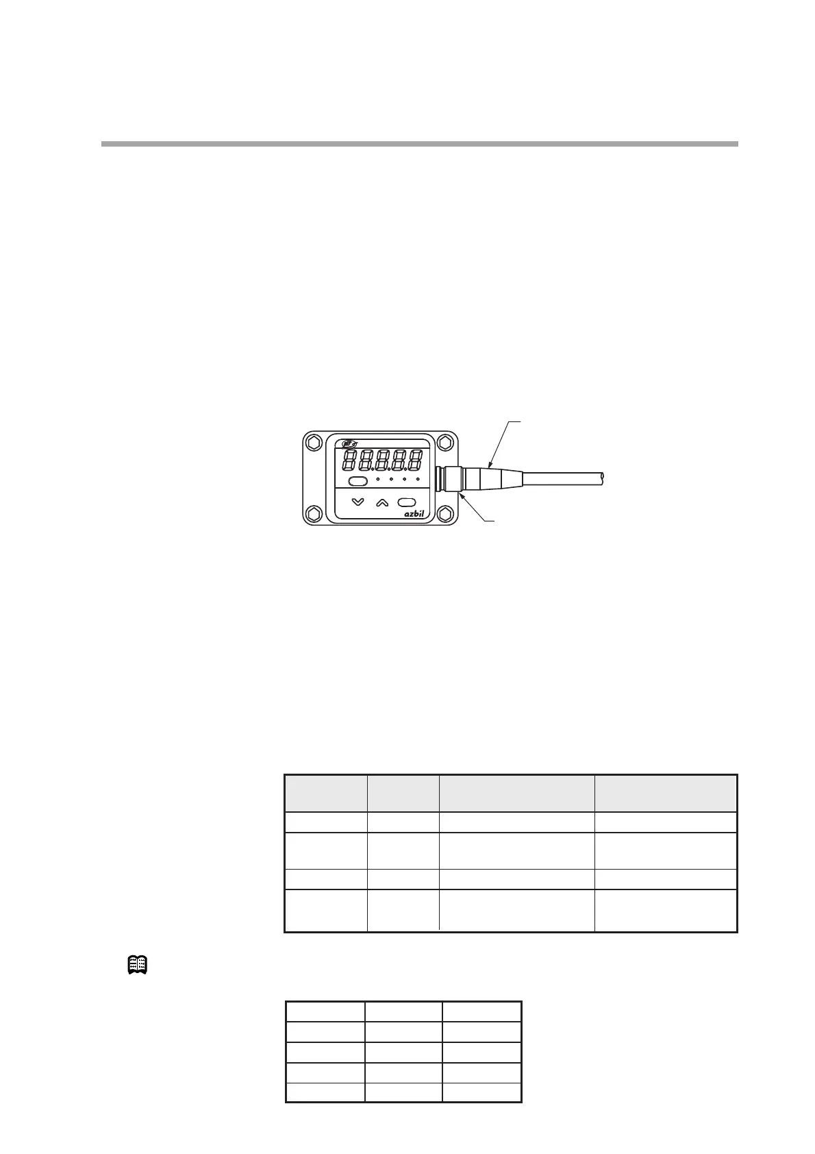
• Do not rotate the cable where it joins the connector (see figure). Doing so might
rotate the connector, twisting and damaging the wires inside.
• Before wiring the MCF, be sure to turn the power off.
• Connect a load with a resistance of not more than 300 Ω for the instantaneous
flow rate output of the 4 to 20 mA output models (MCF_______D01____).
• Keep water away from the cable and from the end of the connector while wiring.
• Be sure to check that the wiring is correct before turning the power on. Incorrect
wiring could cause damage or malfunction.
• Be sure to check the model No. and wiring before turning the power on. The
wiring differs between the 4 to 20 mA output model and the RS-485 communi-
cations model.
● Connector
Note
Wire color and pin number for MCF connector cable
Pin Signal MCF_______D01____ MCF_______D10____
number 4 to 20 mA output model
RS-485 communications model
1V+ 24 Vdc 24 Vdc
2 I+/DB Instantaneous flow RS-485
rate output (4 to 20 mA) communications (DB)
3 COM COM COM
4 EV/DA Event output RS-485
communications (DA)
Pin number Signal Line color
1V+Brown
2 I+/DB White
3 COM Blue
4 EV/DA Black

 Loading...