18
Assembly and Operating Instructions
F2
400 mA
T
S
E
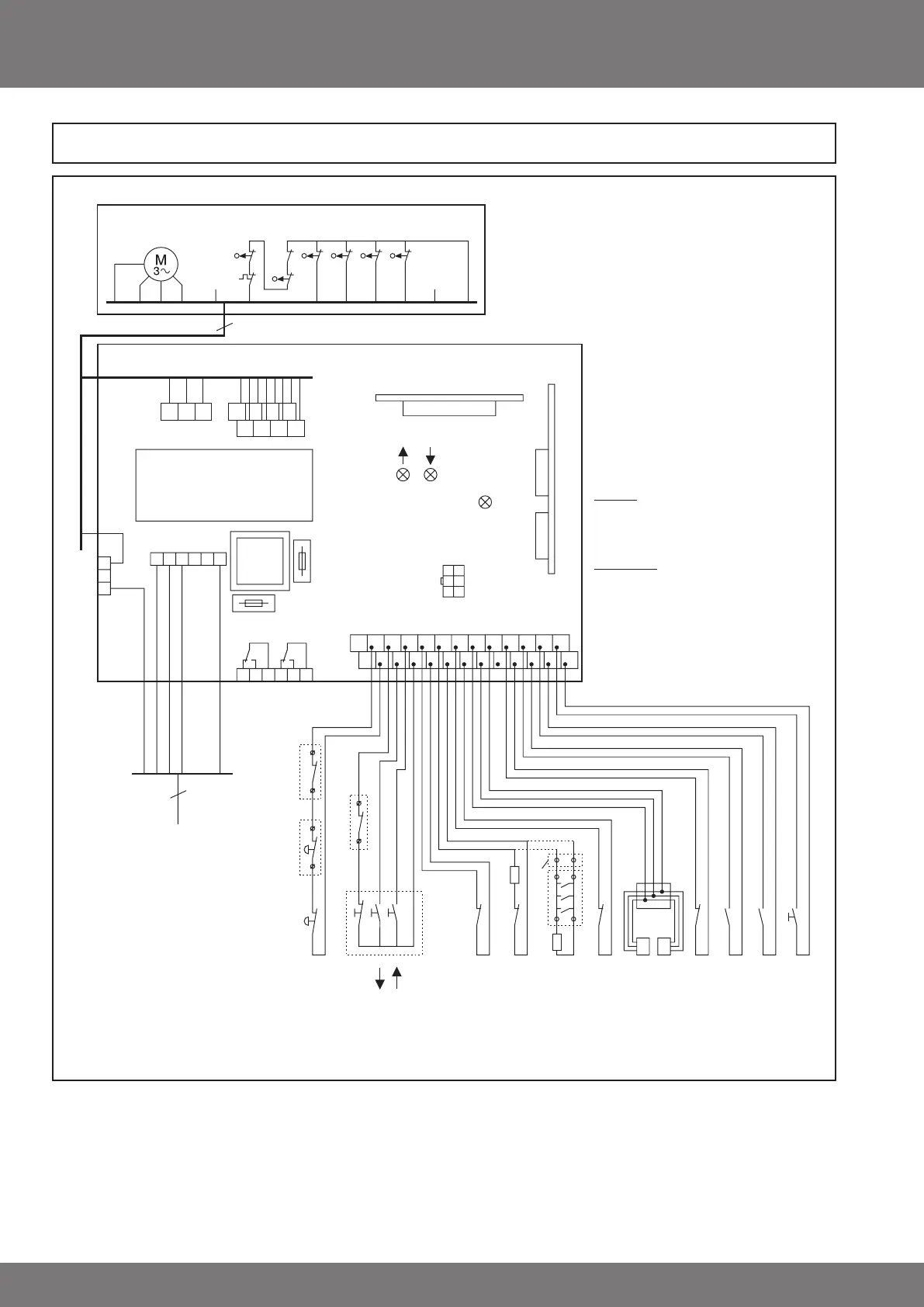
S1F - Safety limit switch OPEN
S2F - Safety limit switch CLOSE
S3F - Safety limit switch Emergency Operation
S4F - Thermal protection switch
S5 - Operation limit switch OPEN
S6 - Operation limit switch CLOSE
S7 - Pre-limit switch Testing
S8 - Function limit switch 1/2 door height
Drive with mechanical limit switching
Drive
S3F
S4F
S1F
S2F
S5 S6 S7 S8
123
4
5 67891011PE
12
Connect according to the numbers indicated
Radio Control
321 4567
8910 11
- 2345678910 11 12 13
- 2345678910 11 12 13
A
B
Relay 1Relay 2
L3 L2 L1 L1 NN
F2
200 mAT
Mains
PE
PE
PE
WVU
Drive
green red
+UB
green
Int. 3-way pushbutton switch
Contactor
24 V DC / 200 mA
Plug-in card
5
3 x 400 V / 230 V AC, 50/60 Hz
SKS/USA
OSE (FRABA)
EL - E
or
DW -
R=1k2 / 8k2
S=Transmitter
E=Receiver
Connection
white=B8
brown=A8
green=A9
lectric safety edge
Safety edge with DW contact (pneumatic)
optical safety edge
slack
rope
switch
External
Emergency
OFF-switch
Emergency
OFF-switch
STOP
STOP
-UP
SKS / USA
Tapping box
R
1.2 kOhm/8.2 kOhm
resistor
LS
FRABA OSE
white=B8
brown=A8
green=A9
Slack rope/
Overload protection
1/2 door height/Stop X
IMP
Wicket door/spring break safety
Ext. 3-way pushbutton switch
R
DW
Trans-
former
AUTO/WZL
General wiring diagram
 Loading...