9
Electrical connection/operation of external control sensors
and safety devices
Note
Before connecting external control sensors you should rst check the direction of door movement and
set the end limits of the door drive.
Voltage output for external control devices (MLS Basic + MLS Professional)
A direct-current voltage is provided at terminals A- and B+ (24 V DC / 200 mA) for external control devices: U = 24 V DC, I
max
= 200 mA. This voltage output is protected by ne-wire fuse F2 with 200 mA slow-blow.
EMERGENCY STOP button (MLS Basic + MLS Professional)
An EMERGENCY STOP button can be connected to terminals A2 and B2. The jumper between terminals A2 and B2 (EMER-
GENCY STOP) must be removed to enable subsequent connection of an external EMERGENCY STOP button.
If the EMERGENCY OFF button is pressed, the drive is switched off. The door is brought to a permanent stop and the +UB LED
goes out. Door movement is only possible again after releasing the EMERGENCY STOP button.
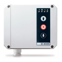
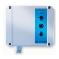
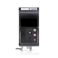
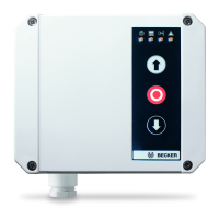
External triple push button (MLS Basic + MLS Professional)
An external triple push button can be connected at terminals A3, B3, A4 and B4 (STOP ↓ ↑). This is identical in function to the
triple push button on the front of the control. The jumper between terminals A3 and B4 must be removed in order to connect
an external triple push button.
Wicket Door Switch / Spring Break Safety Device (MLS Basic and MLS Professional)
A wicket door switch and/or spring break safety device can also be connected across terminals A3 and B4, in series with
the STOP button of the external 3-way pushbutton switch if tted to connect a wicket door switch and/or spring break safety
device, remove the wire jumper across terminals A3 and B4.
Induction loop (MLS Basic + MLS Professional)
An induction loop for automatic door opening can also be connected at terminals A4 and B4, possibly in parallel with the
UP button of the external 3-way pushbutton. If possible, the induction loop should be set so that it gives a CONTINUOUS UP
COMMAND.
Slack Rope Switch (MLS Basic + MLS Professional)
A slack rope switch can be connected across terminals A10 and B10 (SCHLAFFSEIL/ÜL). For installation the wire jumper
across terminals A10 and B10 must be removed. This input is debounced via an internal timing element of approx. 0.1 s (de-
pending on the bounce of the switch). If the slack rope switch responds beyond that time, the door stops instantly no matter
what position it is in. All other door movements are inhibited for as long as the switch is being operated.
Caution
The “slack rope switch” input is not monitored to such an extent that errors can be ruled out. If a combined
slack rope/trap switch is used, this must be connected to the terminals A2 and B2 EMERGENCY-OFF.
Pull in safety cable/switch (MLS Basic and MLS Professional)
A safety switch can be connected across terminals A5 and B5 (STOP-UP) to prevent the curtain from being drawn in the UP
direction. For installation the wire jumper across terminals A5 and B5 must be removed. If this safety device responds during
upward movement, the door stops instantly. Upward movement remains inhibited. The door now has to be moved to the bot-
tom end limit manually by pressing the DOWN button (↓).
Light barriers in use must comply with safety category 3 according to EN 954.
Only applies to MLS Professional Card
The control unit switches to the dead-man mode (inching mode). Only when the bottom limit position has been reached does
the control unit switch back to automatic mode.
External 1-way Switch (MLS Professional only)
An external 1-way pushbutton switch can be connected across terminals A13 and B 13 (IMP). The pushbutton commands
are executed one after the other in the sequence UP - STOP - DOWN - STOP (pulse-edge evaluation when the button contact
closes). If there is a fault, the pushbutton commands are executed one after the other in the sequence UP - STOP - UP.
Partial Opening (MLS Professional only)
A switch can be connected across terminals A11 and B11 (half the door height) in order to activate the Partial Opening func-
tion (also called half door height). If Partial Opening is activated, the setting of limit switch S8 (green cam) of the drive serves
as the top end limit.
 Loading...