Commissioning
CP39xx36 Version: 3.6
4.3.2 Routing the cables in the mounting arm adapter
NOTE
Cable damage due to incorrect cable routing
Incorrect cable routing can cause cable damage when rotating and tilting the mounting arm adapter.
• Be sure to route the cables inside the mounting arm adapter in the specified arrangement.
Depending on the device equipment, the connections are either located at the connection block on the rear
side of the control panel or inside the mounting arm adapter. If you have ordered the control panel with one
of the following Beckhoff mounting arm adapters installed ex factory, it is essential that you observe the
cable routing shown (see Fig. 28) in order to avoid cable damage:
• C9900-M750
• C9900-M751
• C9900-M752
• C9900-M753
1
2
A B
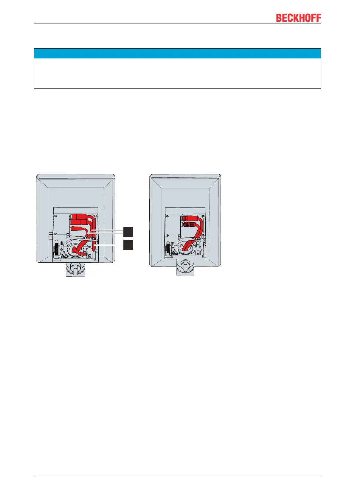
CP39xx-0000 CP39xx-0010
Fig.28: CP39xx_Mounting arm adapter cable routing
For the CP39xx-0000 (section A) you have to route the power supply cable (1) further outside and the data
cables (2) inside. You must fix the cables to the strain relief rail with cable ties as follows:
• Attach the power cable (1) to the far right of the strain relief rail by pulling the cable tie through the two
outer right straps of the rail.
• Attach the data cables (2) to the far left of the strain relief rail, using a cable tie to secure both cables
together. To do this, use the left and the third strap from the left.
For the CP39xx-0010 (section B) you have to route all cables inside. If you use the CU8803 transmitter box,
you only have one cable, which you also have to lay inside. You must fix the cables to the strain relief rail
with cable ties as follows:
• In the case of two cables use a cable tie to secure both cables together on the far left of the strain relief
rail. To do this, use the left and the third strap from the left.
• In the case of one cable pull the cable tie through the two outer left straps on the far left of the strain
relief rail.
When routing the cables for both device versions, follow the steps below as shown in figure 29:
1. Loosen the Torx TX20 screw of the strain relief rail (section A).
2. Rotate the strain relief rail by 180° to the left (section B).
3. Route the signal and power supply cable inside the mounting arm adapter as shown in Figure 28.
4. Route the data cables inside the mounting arm adapter as shown in figure 28.
 Loading...