Product overview
EL34xx26 Version: 1.5
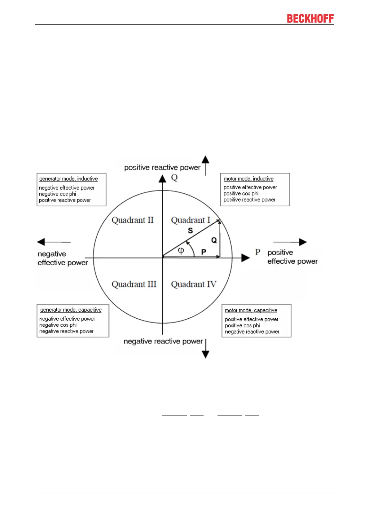
Sign for power measurement
The sign of the (fundamental wave) active power P and the power factor cos φ provides information about
the direction of the energy flow. A positive sign indicates the motor mode, a negative sign indicates
generator mode.
Furthermore, the sign of the fundamental harmonic reactive power Q provides information about the direction
of the phase shift between current and voltage. Fig. Four-quadrant representation of active/fundamental
harmonic reactive power in motor and generator mode illustrates this. In motor mode (quadrant I + IV), a
positive fundamental harmonic reactive power indicates an inductive load, a negative fundamental harmonic
reactive power indicates a capacitive load. The information about a capacitive or inductive load behavior is
also shown in the sign of the phase angle φ, which is already contained in the EL3443.
In generator mode (quadrant II & III), an inductive generator is indicated by a positive fundamental harmonic
reactive power, a capacitive generator by a negative fundamental harmonic reactive power.
Since the total reactive power is defined as the quadratic difference between apparent and active power, it
has no sign. For the total active power, signs are permitted, as described above.
Fig.17: Four-quadrant representation of active power/fundamental harmonic reactive power in motor and
generator mode
Frequency measurement
The EL34xx can measure the frequency for a voltage path input signal and a current path input signal. CoE
objects "Reference" and "Frequency Source" (F800:11 [}159] and F800:13 [}159]) can be used to set which
frequency is to be output as PDO.
Power quality factor
The EL34xx calculates a PQF (power quality factor), which reflects the quality of the voltage supply as a
simplified analog value between 1.0 and 0.
To calculate this factor, the measured values, frequency, RMS voltage, distortion factor and voltage
imbalance are calculated and combined as shown in the following diagram.

 Loading...