17
8 CALIBRATION OF TRAVEL LIMITS
The actuator is factory-set for a 90° travel.
It features 2 devices to limit the travel:
• Cams trigger switches to switch off power at an end position
or to signal a position. They are factory pre-set, but you can
re-adjust them during commissioning if necessary.
• Mechanical stops mechanically limit rotation to protect the
valve in case of over-travel.
8.1 Calibration of cams corresponding to end position
switches
The actuator stops on the open and closed positions when the
corresponding end position switch is tripped.
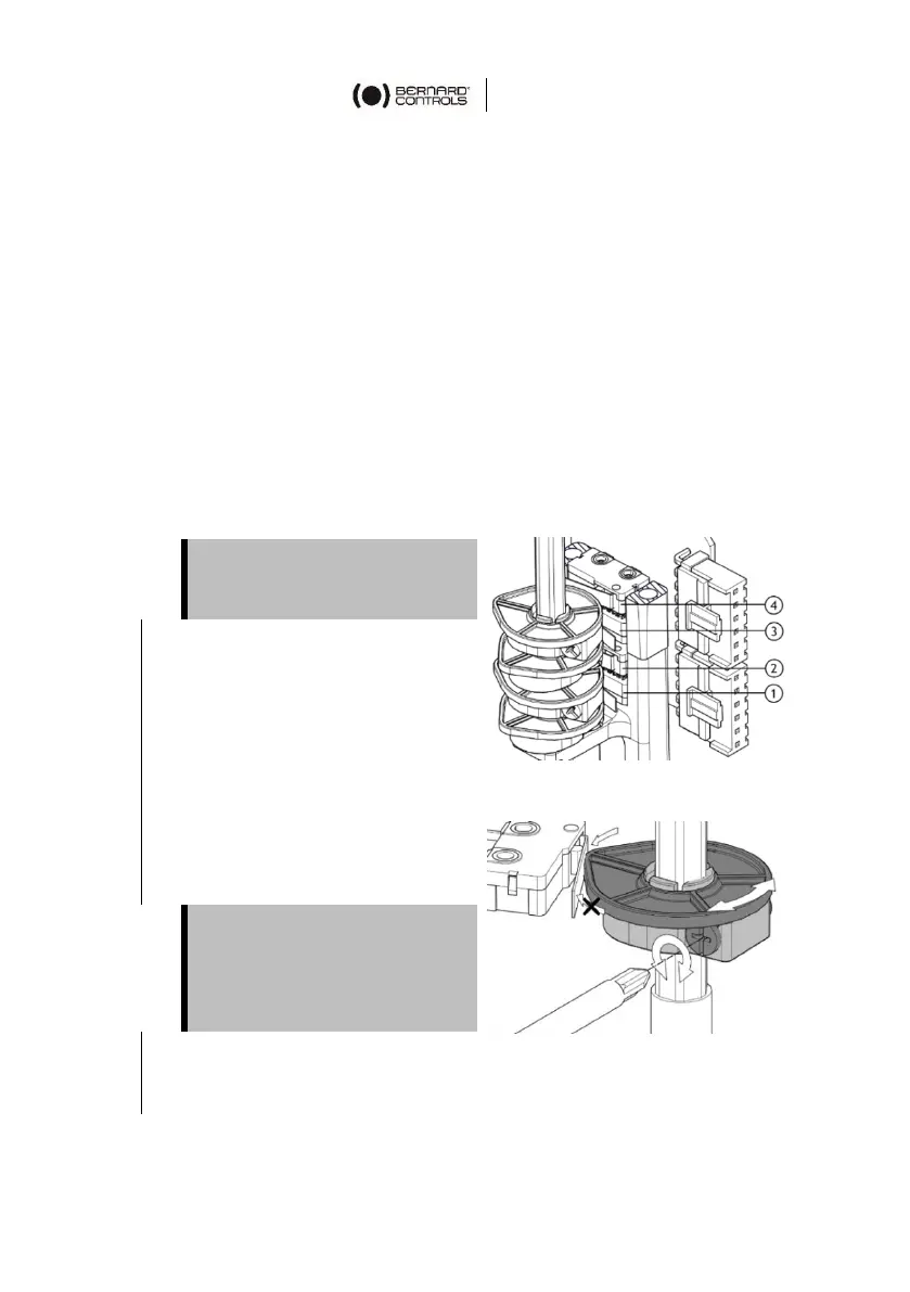
1. Turn the setting screw of
the blue cam corresponding
to the clockwise travel limit
switch (1 in Figure 1) with a
screwdriver (see Figure 2).
The cam disk is then turning.
2. Set the cam disk until you
hear a click from the switch.
It indicates that the switch
has been triggered.
3. Perform a short electrical
counterclockwise
operation, then go clockwise and stop on the switch.
Make sure that the cam
operates the lever in the right
direction (as shown by the
arrow in Figure 2), otherwise
the switch could be damaged.
 Loading...