23
9.2 TAM position transmitter (OPTION)
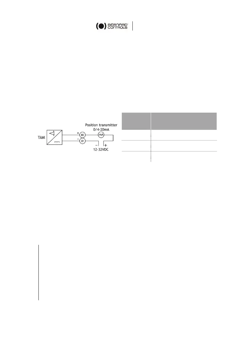
The TAM transmitter delivers a 4 to 20 mA signal that is linearly
proportional to the angular position of the valve.
Electrical connections
See Chapter 11 for more information on the wiring.
A filtered or stabilized power supply should be provided within the
12 to 32 VDC range. Maximum admissible resistance values are given
in the following table:
Signal direction inversion
The TAM transmitter, when supplied with a clockwise closing
actuator, provides a signal that rises from closed position to open
position.
If an opposite signal variation is required, simply move 2 jumpers on
the board near the potentiometer:
• direct signal: jumpers on 1-3 and 2-4
• reversed signal: jumpers on 1-2 and 3-4
How to set TAM
1. Connect a milli-amp meter on the terminal block and bring
power (24 VDC).
2. Always start by adjusting the 4 mA.
3. Drive the actuator to the position corresponding to 4 mA
(CLOSED position).
4. Loosen the potentiometer pinion blocking screw with a hex
key.

 Loading...