18 19
14.2 AUTOMATIC SET UP
Select set up in the MENU and turn to OK to confirm.
Select closing mode in the SET UP menu and turn to OK
to confirm. Select whether valve to close on basis of torque
or position both open and close actions can be set on torque).
Turn to OK to confirm. When close direction is displayed turn
to OK to confirm. Indicate normal close direction (generally
clockwise).
Turn to OK to confirm.
When position setting is displayed turn to OK to confirm.
Select automatic on POSITION SETTING menu
The automatic setting cycle begins when the user
turns to OK.
The actuator detects the end positions by means of the torque limiter and then positions itself at
mid-stroke to test its inertia in both directions of travel.
INTELLI+ determines stop positions at 0 and 100% on the basis
of the closing mode setting and the actuator inertia.
The display shows the stroke travel distance at the end of the
set up process
Turn to OK to confirm and return to control mode.
15 POSITION SIGNAL AND POSITIONER
Position signal
Some actuator configurations can incorporate an analogue position signal.
No prior set up is required as the signal is automatically adjusted to the 0 to 100% positions. The
default signal is in 4-20 mA format (4 mA at 0% and 20 mA at 100%)
2 or 3-wire connections.
See §25 for further details and information on analog signals.
Positioner
Some actuator configurations can perform control functions in response to a control signal
(e.g. 4 – 20 mA). No prior set up is required as the signal is automatically adjusted to the 0 to 100%
positions.
To check positioning locally, local control has to be configured for proportional
control from 0 to 100%. When this setting has been completed, return to the
local control mode.
The display shows the opening position and the command in %.
Adjust the control value up or down with the blue button and ensure that the actuator adopts
the position required.
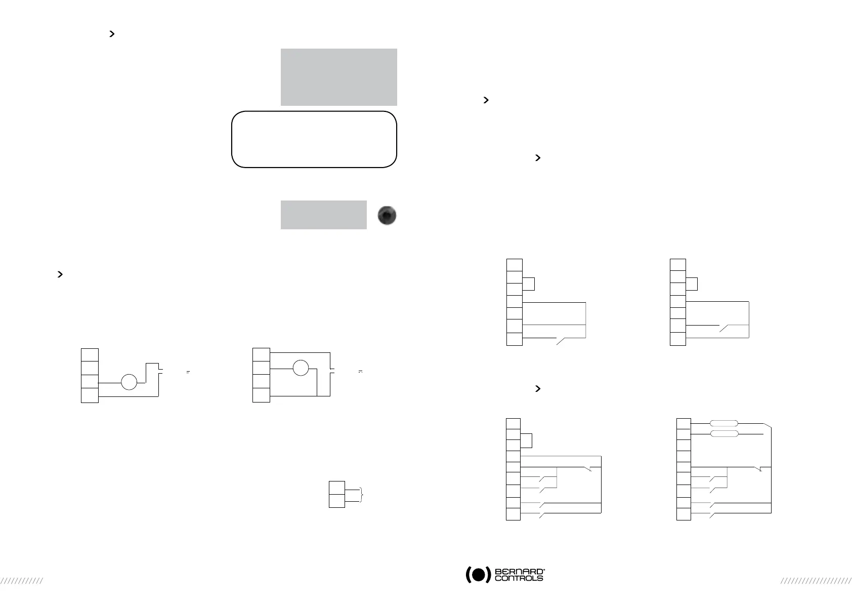
measured stroke
37 turns
ok
Note: The cycle can be
halted immediately during automatic
set up. Use the local stop command
to return to the menu .
This action cancels the set up procedure.
Warning: during automatic
setting the actuator halts on
mechanical stops so take care
according the type of valves
you are commissionning
32
33
34
35
2 wires connection
12 - 32V
mA
+
-
+
-
32
33
34
35
3 wires connection
12 - 32V
mA
+
-
+
-
30
31
-
+
4 - 20 mA
0 - 20 mA
0 - 10 V
One of the auxiliary commands has to be set to AUTO / ON-OFF to operate remotely (see §16.3).
The actuator is on positioner control when this setting has been completed. The auxiliary command
must be switched for On-Off commands. This auxiliary command is used for selecting positioner or
on-off control remotely.
See §26 for further details, particularly regarding deadband settings.
16 COMMANDS
Standard remote command modes are described in §7 above. This section covers additional control
methods.
16.1 REMOTE CONTROL VIA SINGLE CONTACT
The actuator can be controlled via a single external contact.
- Contact closed: valve opens
- Contact open: valve closes
The actuator has to be configured for priority to open (see §16.6)
The command can be made the other way round:
- Contact closed: valve closes
- Contact open: valve opens
In this case, the actuator has to be configured for priority to close (see §16.6)
16.2 AUxILIARY REMOTE CONTROLS
Two further remote commands are available and can be configured for the installation.
These commands can be assigned to specific functions.
4
5
6
7
8
9
10
OPEN
Opening by single
contact closing
4
5
6
7
8
9
10
CLOSE
contact closing
Configuration: priority to open
Configuration: priority to close
CLOSE
OPEN
Aux. command 1
Aux. command 2
STOP
4
5
6
7
8
9
10
11
12
CLOSE
OPEN
Aux. command 1
Aux. command 2
STOP
4
5
6
7
8
9
10
11
12
90 - 160V*
10 - 55V
*160 to 250V in option
 Loading...