3
1 Safety information Page 3
1.1
Marking Page 3
1.2
Installation Area Page 4
1.3 Cautions for electrical connection Page 5
1.4 Operation Page 6
1.5 Maintenance Page 6
1.6 Electrical and temperature parameters Page 7
1.7 Special operation conditions including unconrrect practices Page 7
1.8 List of applicable standards Page 7
2 Product overview Page 8
3 Storage Page 9
4 Actuator on valve assembly Page 9
5 Electrical connection Page 10
6 Actuator on valve setting introduction Page 10
7 Remote control Page 11
7.1 Dry contact control Page 11
7.2 Voltage control Page 11
8 Local control using buttons and display Page 12
9 Navigating in the menus Page 12
9.1 Selectors Page 12
9.2 Main menu Page 13
9.3
Select a menu or an option Page 13
9.4
Saving the changes Page 13
9.5 Exiting the menu at any times Page 14
9.6 Main menu description Page 14
10 Selecting the display language Page 14
11
Password Page 14
12
Check menu flowchart Page 15
13 Set up and change menu flowchart Page 16
14 Adjusting an actuactor on a valve Page 17
14.1 Manuel set up Page 17
14.2
Automatic set up Page 18
15
Position signal and positioner Page 18
16 Commands Page 19
16.1 Remote control via single contact Page 19
16.2 Auxiliary remote controls Page 19
16.3 Local commands Page 21
16.4 Local stop Page 21
16.5
Remote stop Page 21
16.6
Open or close priority Page 22
16.7 ESD in degraded mode Page 22
16.8 Partial stroke Page 22
17 Local communication with PC Page 23
16.1
Infrared communication Page 23
16.2
Bluetooth communication Page 23
18 Setting and viewing torque values Page 24
18.1 Closing type Page 24
18.2 Torque setting Page 25
18.3
Torque reading and comparison with original torque values Page 25
19
Customizing status and control indications Page 26
19.1 Local indication Page 26
19.2 Remote indications Page 27
20 Customizing fault relay Page 28
21
Timing movement travel Page 29
22
Viewing actuator history Page 30
22.1 Activity Page 30
22.2 Alarms Page 30
23 Accessing data sheet Page 31
24
Creating or changing password Page 32
25
Using analogue position signal (depending on model) Page 32
26 Use as a positioner with an analogue control signal (depending on model) Page 33
26.1 Input signal Page 33
26.2 Setting of deadband value Page 34
26.3
Fail-safe position Page 34
26.4
Proportional pulse mode Page 34
27 Using fieldbus control (depending on model) Page 34
28 Using in case of power supply lost (with battery depending on model) Page 35
29 Fuse protection Page 36
30
Using in separated box Page 36
31
Maintenance Page 36
32 Troubleshooting Page 37
32.1
Intelli+ Page 37
32.2
Positioner option Page 39
CONTENTS
1 SAFETY INFORMATION
The following documents should also be consulted:
a) IEC/ EN60079-14 standard (electric installations in gaseous explosive atmosphere),
b) IEC/EN60079-17 standard (inspection and maintenance operations in dangerous areas),
c) For USA, NFPA70 National Electrical Code®
d) Decrees, ministerial orders, laws, directives, standards, procedures and any other document
relative to the area where the actuator has to be installed.
BERNARD CONTROLS cannot be judged responsible for the non-respect of these rules.
Our actuators have been designed for a use in hazardous (Classified) locations:
Zone 1 and 2 : Gaz Group II
Zone 21 and 22 : Dust
Actuators CSA marked : our equipments comply with CSA certifications - CSA zones
Actuators INMETRO CEPEL marked : our equipments comply with the INMETRO CEPEL certification
Divisions 1 : Gaz Class I / Dust Class II
Actuators CSA marked : our equipments comply with CSA divisions c and us certifications
(CSA and FM standard)
Please check the compatibility between the indications written on the identification plate and the
explosive atmosphere type, the ambient and the admissible surface temperature of the installation area.
The actuator installation and maintenance must be carried out by qualified, trained and certified
personnel.
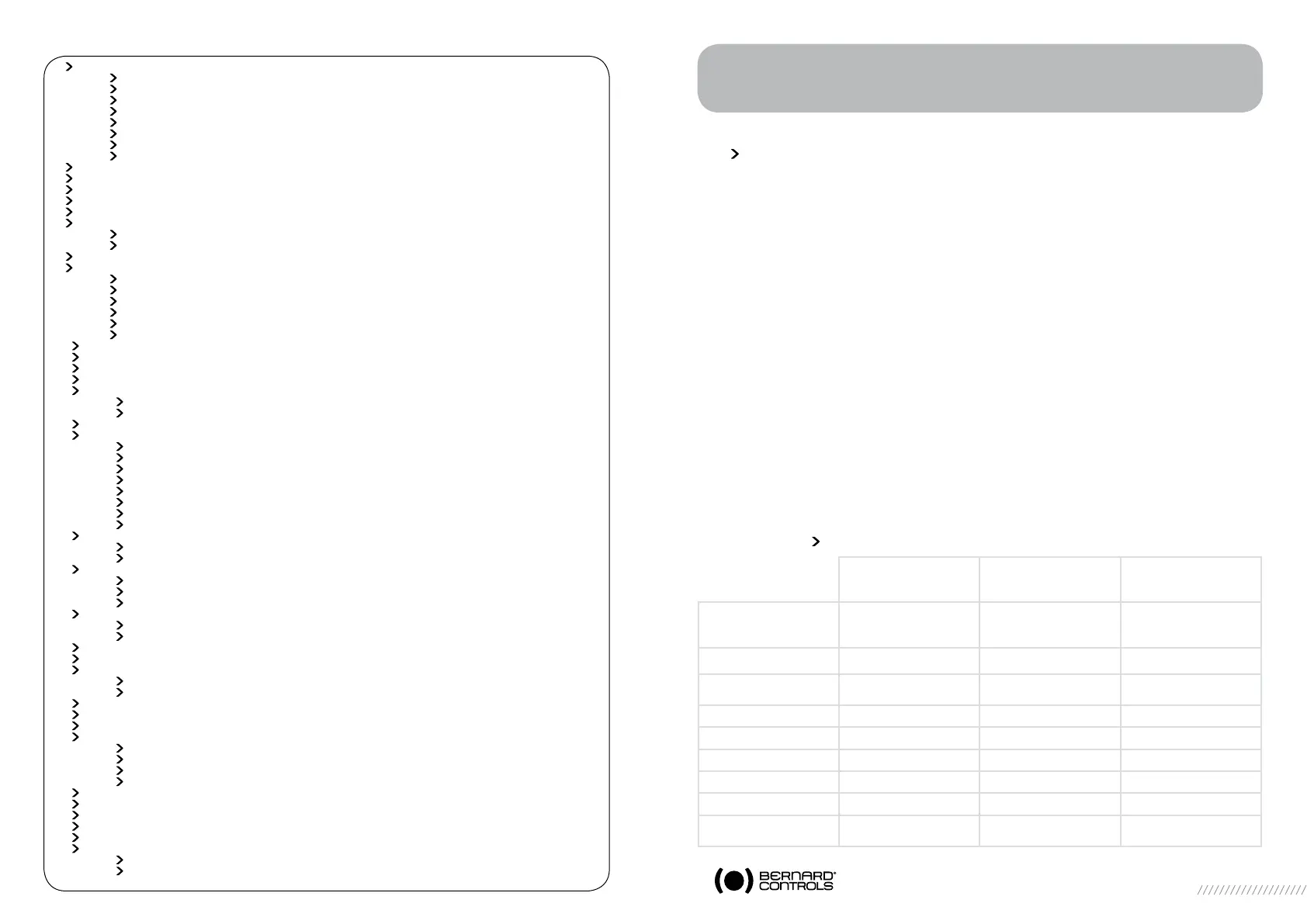
1.1 MARKING
WARNING
READ THESE INSTRUCTIONS CAREFULLY BEFORE USE
CSA zones
Explosionproof
enclosure “d”
IEx
Explosionproof
enclosure “d”
CSA divisions
Explosionproof
Name and address
of the manufacturer
BERNARD CONTROLS
4 rue d’Arsonval 95505
Gonesse France
BERNARD CONTROLS
4 rue d’Arsonval 95505
Gonesse France
BERNARD CONTROLS INC
4 rue d’Arsonval 95505
Gonesse France
Actuator type Type STX... Type STX... Type STX...
Serial number and year of
construction
99605 001 - 2011 99605 001 - 2011
Certificate number CSA Zone IEx CSA division
Specific marking CSA c and us
Notified audit body CSA CSA
Gaz marking Ex d IIB T4 Gb Ex d IIB T4 Gb Class I div1, Gr C, D, T4
Dust marking Ex tb IIIC T135°C Db Ex tb IIIC T135°C Db Class II div1, Gr E, F, G
Ambiant
temperature
-4°F +158°F -20°C +70°C -4°F +158°F
 Loading...