10 11
5 ELECTRICAL CONNECTION
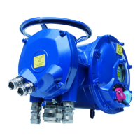
Only the cover of the connection box/compartment (Fig. 2) requires to be open for electrical connec-
tion. The other covers should not be removed at the risk of introducing moisture into the electronic
controls.
A wiring diagram is normally supplied with the actuator. If
this is not the case, please ask our customer service.
Operating procedure :
a) Check the power supply characteristics with respect to
the rating nameplate. In 3 phase, the phases order is not
important as the INTELLI+ system corrects the direction
of rotation automatically.
b) Open the terminal box (fig. 2), connect the power and
control circuits (ring tongue not supplied). The screw dia-
meters is 3mm for the control and 4mm for the power.
Check the wiring.
c) make sure that the cover screws, cable glands are pro-
perly tighten and IP68 waterproofness is assured by an
O ring or by a thread sealant as noticed §1.3.
6 ACTUATOR ON VALVE SETTING INTRODUCTION
Each INTELLI+ actuator is set and checked at the factory.
If the actuator is delivered mounted on top of a valve, the open and closed positions as well as the
maximum torque values should have been adjusted by the valve supplier.
If an actuator on valve setting has to be performed or optimised, it can be done by simply connec-
ting the power supply. All settings and configurations can then be performed in a non-intrusive way
using the blue and red rotating knobs together with the graphical display.
The following chapters of this document include all the information necessary to perform actuator
on valve settings:
§9. NAVIGATING IN THE MENUS
§10. SELECTING THE DISPLAY LANGUAGE
§18. SETTING AND VIEWING TORQUE VALUES (in case of closing on torque)
§18.1 Closing type
§18.2 Torque setting
§14. ADJUSTING AN ACTUACTOR ON A VALVE
7 REMOTE CONTROL
The INTELLI+ actuator’s remote control system can be operated using an external or an integral
voltage supply.
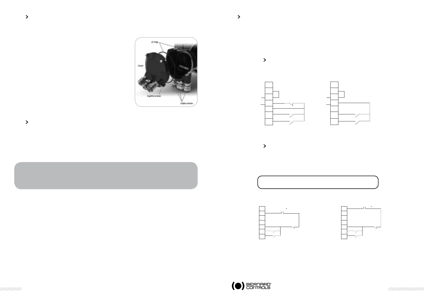
The input circuits are fully opto-isolated. The self-hold pulse command system requires four connec-
ting wires on the client terminal strip: Common, stop, open and close. If the stop push-button is not
used, do not connect the STOP wire, open (or close) contact must be maintained to operate the
actuator.
7.1 DRY CONTACT CONTROL
In case of dry contact control, a jumper must be fitted across customer terminal 5-6.
7.2
VOLTAGE CONTROL
Remote control can use either in AC or DC voltage.
Use common terminal 5 for low voltages from 10 to 55V.
Use common terminal 4 for voltages from 90 to 160V (250V with optionnal insulation).
Caution: never connect voltage sources above 55V
on common terminal 5.
WARNING
On quarter-turn actuators, mechanical end stops, located either on the actuator or the
gearbox, mechanically limit the actuator travel during manual operation.
It is mandatory that the motor stops, in both directions, on the travel limit switch and not
on the mechanical end stop (check available extra travel to the stop with the handwheel).
24V
1,2W
-
+
4
5
6
7
8
9
10
STOP
CLOSE
OPEN
Pulse remote command
(self-holding)
24V
1,2W
-
+
4
5
6
7
8
9
10
CLOSE
OPEN
Remote command
without self-holding
(fig 2)
4
5
6
7
8
9
10
CLOSE
OPEN
To cancel self-holding
do not connect terminal 8
10 - 55V ~
4
5
6
7
8
9
10
CLOSE
OPEN
90 - 160V* ~
STOP
STOP
*160 to 250 V in option
 Loading...