EN/9
Retrofit / Installation kit No. 65 90 0 027 973 (others see cover sheet)
Installation Instructions No. 01 29 0 140 447 Issue date: 06.2001
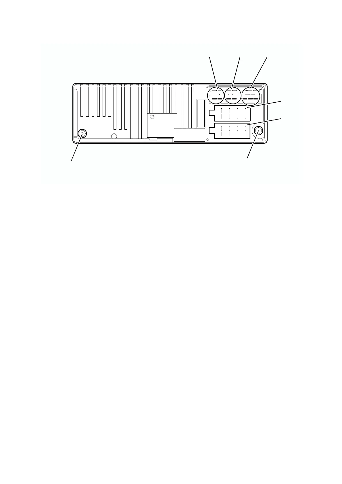
7. Navigation radio connection diagram
0
Legend
0
Chamber A Chamber C2
1 Speed signal (TAA) 7-12 Specific connection for CD
changer
2 Signal from reversing light
3 Telephone mute
Chamber C3
4 Continuous positive (terminal 30) 13 Low frequency telephone input
5 Control output for automatic aerial/amplifier 14 Earth telephone input
6 Light (terminal 58G) 15-17 Specific connection for CD
changer
7 Switched positive (terminal 15) 18 CD low frequency earth (AUX)
8 Earth (terminal 31) 19 CD low frequency left (AUX)
20 CD low frequency right (AUX)
Chamber B
1 Speaker rear right+
Jack D
2 Speaker rear right- Radio aerial jack
3 Speaker front right+
4 Speaker front right-
Jack E
5 Speaker front left+ GPS aerial jack
6 Speaker front left-
7 Speaker rear left+
8 Speaker rear left-
Chamber C1
1 LineOut rear left
2 LineOut rear right
3 Low frequency earth
4 LineOut front left
5 LineOut front right
6 Subwoofer LineOut
1 4 7 10 13 16 19
3 6 9 12 15 18
2 5 8 11 14 17 20
1 3 5 7
2 4 6 8
1 3 5 7
2 4 6 8
10
10
B
A
E
C3
C2
C1
D
039 0021 B
 Loading...