69
E90 General Vehicle Electrical
Examples: The following examples illustrate the interaction of the individual compo-
nents for the power windows function.
Switch Cluster, Driver's Door
1. The signal is routed via the LIN-bus to the footwell module when the power window
switch for the window in the driver's door or front passenger's door is operated. The
footwell module drives the corresponding power window motor.
2. The signal is routed from the driver's door switch cluster via the LIN-bus to the footwell
module when the power window switches for the windows in the rear doors are operated.
The FRM sends the signal via the K-CAN to the JBE.
On receiving the signal, the Junction Box Electronics Control Module activates the corre-
sponding power window motor.
Power window switch, front passenger's door
The signal is routed to the JBE when the power window switch in the front passenger's
door is operated. The JBE sends the signal via the K-CAN to the footwell module. The
FRM drives the power window motor.
Power window switch, rear doors
The signal is routed to the JBE when the power window switches in the rear doors are
operated. The JBE drives the power window motor.
By way of example, the opening and closing procedure for one of the rear windows is
illustrated in the signal progression in the following graphic. The opening or closing func-
tion is initiated from the driver's door switch cluster.
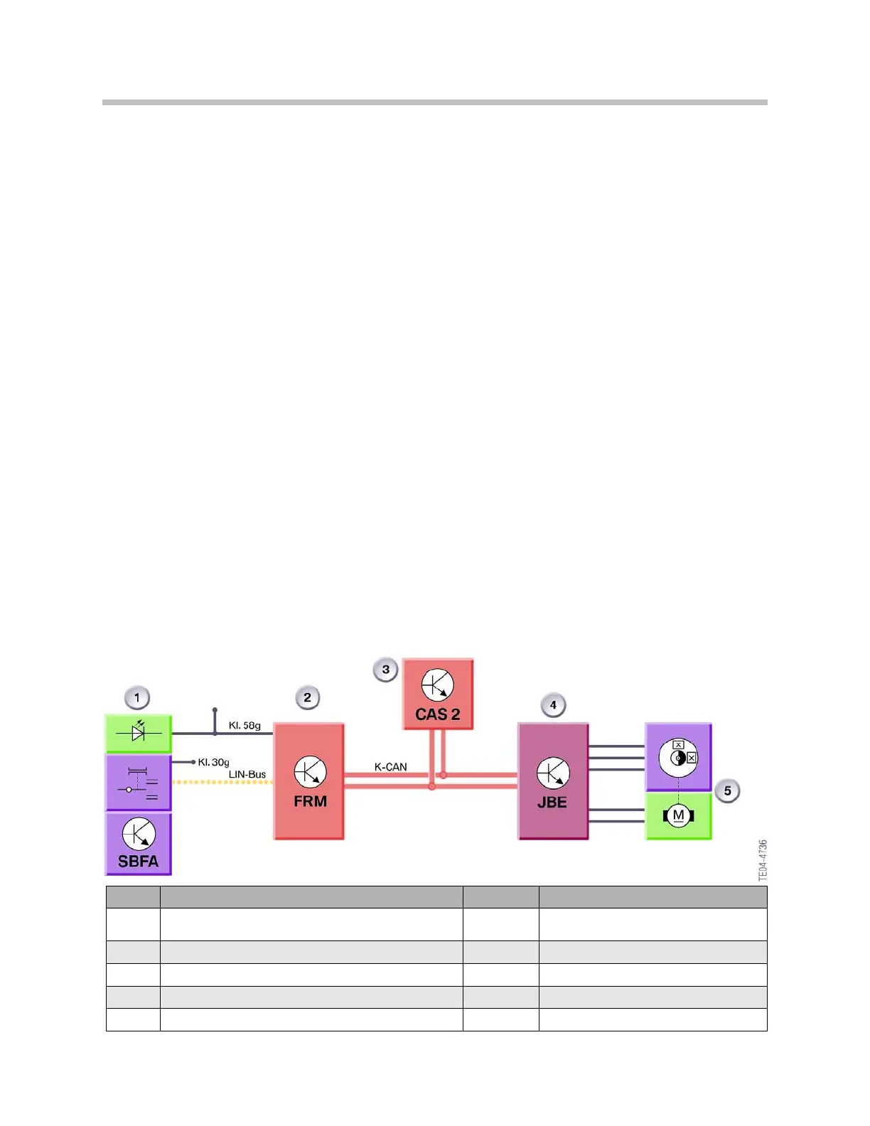
Index Explanation Index Explanation
1
Power Window Switch in Driver's Door switch cluster
SBFA
LIN-Bus
Lin-Bus
2
Footwell Module (FRM)
K-CAN
Bodyshell CAN
3
Car Access System 2 (CAS 2)
Kl. 30g
Terminal 30g
4
Junction Box Electronics Control Module (JBE)
Kl. 58g
Terminal 58 g
5
Power Window Motor

 Loading...