1 689 975 252 2019-05-15| Robert Bosch GmbH
22 | ACS 511 | Service phasesen
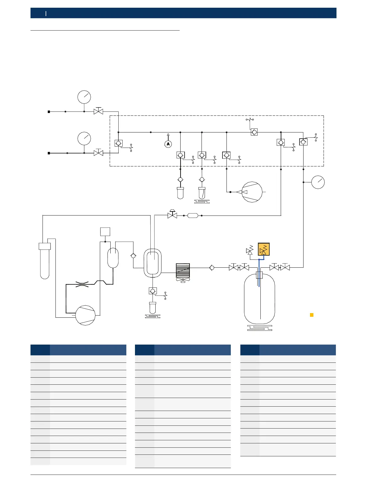
8.10 Non-condensing gases
i The drain valve (V6) for non-condensing gases opens
if the pressure in the refrigerant cylinder is higher
than the set opening pressure (normally between 12
and 14 bar).
i The pressure of the internal refrigerant cylinder in-
creases during the recovery phase and when prepar-
ing the refrigerant.
i The safety valve (V5) opens at a factory set pressure
(approx. 18 bar) to limit the pressure in the internal
refrigerant cylinder.
EV5
EV3
EV6
3F1
C
P2
HP
5
VU2
6
F2
9
4
EV7
10
7
V1
8
V3 V2V4
V6V5
M1
M3
EV10
P
M2
HIGH
LOW
P1
T1
T2
2
EV1
11
VU3VU1
12
1
EV8EV9
13
active
Name Description
1 Fresh oil tank
2 Vacuum pump
3 Expansion valve
4 Evaporator/oil separator
5 Compressor oil separator
6 Compressor
7 Internal refrigerant cylinder
8 Refrigerant cylinder scales
9 Used oil bottle
10 Heat exchanger
11 UV dye bottle
12 Fresh oil scales
13 Used oil scales
EV1 Vacuum solenoid valve
EV3 Flow solenoid valve
Name Description
EV5 Recovery solenoid valve
EV6 Filling solenoid valve
EV7 Oil drain solenoid valve
EV8 Oil injection solenoid valve
EV9 Contrast medium injection sole-
noid valve
EV10 Solenoid valve for separating
high and low pressure
F1 Coarse filter
F2 Combi filter
HP High pressure
LP Low pressure
M1 Low pressure gage
M2 High pressure gage
M3 Internal refrigerant cylinder pres-
sure gage
Name Description
P1 Pressure sensor
P2 Pressure switch
T1 Low pressure hose
T2 High pressure hose
V1 Tank vapour side hose valve
V2 Tank liquid side hose valve
V3 Tank vapour side valve
V4 Tank liquid side valve
V5 Safety valve
V6 Non condensable drain valve
VU1 Oil non-return valve
VU2 One-way valve
VU3 UV contrast medium non-return
valve

 Loading...