Product description
5
Compress 3400iAWS E – 6721852787 (2023/01)
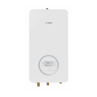
2.5.1 Generic overview of the refrigerant circuit
Fig. 1 Functional principle of the refrigerant circuit in the heat pump
[1] Evaporator
[2] Compressor
[3] Condenser
[4] Expansion valve
2.6 Indoor unit
The purpose of the indoor unit is to distribute the heat from the outdoor
unit to the heating system and DHW cylinder. The speed of the circulation
pump in the indoor unit is controlled so that it automatically reduces
when demand is low. The energy consumption falls as a result.
If the heat energy demand is higher at low outside temperatures, an
auxiliary heater may be required. Auxiliary heaters can be integrated or
external and are switched in or disconnected automatically by the user
interface in the indoor unit. If the outdoor unit is in operation, the electric
booster heater only produces enough heat to make up the shortfall
between the outdoor unit output and the required heat. As soon as the
outdoor unit is once again producing the required output on its own, the
auxiliary heater is switched off automatically.
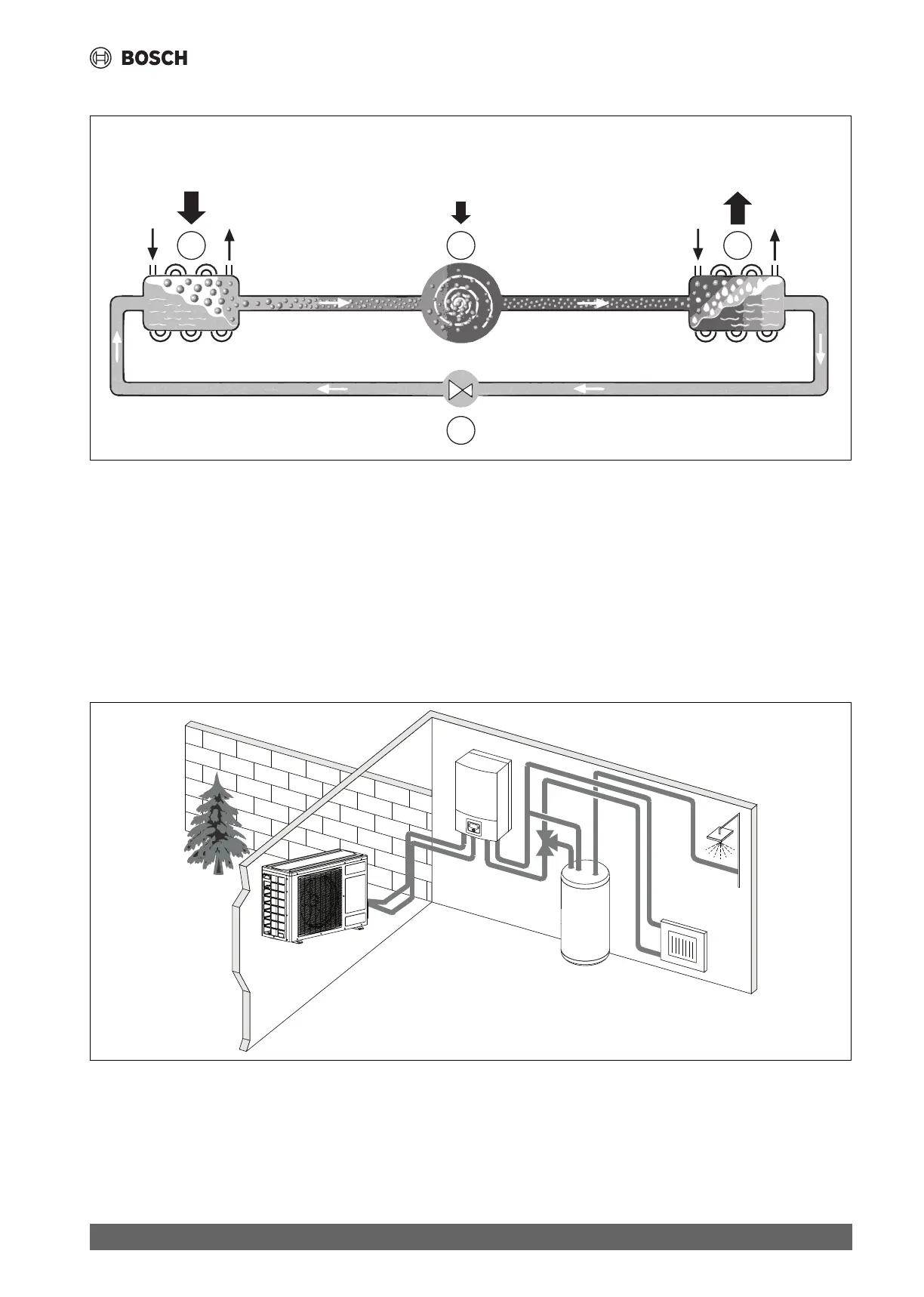
AWS E
When the outdoor unit is combined with the indoor unit AWS E and DHW
is also to be produced via the heat pump, an external DHW cylinder must
be connected. The changeover between heating and DHW is then
effected by an external 3-way valve. The integrated electric booster
heater in the indoor unit is started if required.
Fig. 2 Heat pump outdoor unit, indoor unit AWS E with electric booster heater and external DHW cylinder
+27 °C
75 %
+35 °C+2 °C –2 °C
0 °C 88 °C
–4,5 °C 50 °C
25 %
100 %
1
2
4
3

 Loading...