EN | 67
D9412G/D7412G | Operation & Installation Guide |
Bosch Security Systems | 10/03 | 43488E
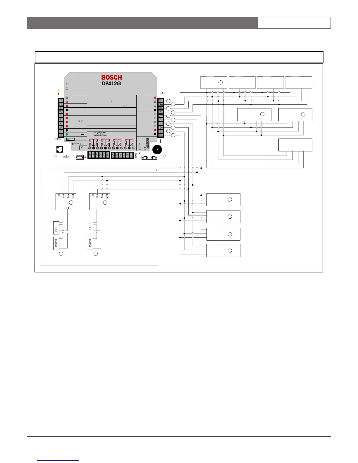
Appendix A
Figure 36: D9412G System Wiring Diagram, 3 of 3
EARTH GROUND
COMMO N
BATTERY NEGATIVE ONLY
Maximum Char ging
Current 1. 4 Amps.
BATTERY POSITIVE ONLY
RELAY A
RELAY B
RELAY C
+ AUX POWER
1
2
3
4
5
6
7
8
9
10
CLASS 2 TRANSFORMER
16.5 VAC 40 VA 60 Hz
Model D1640
Internally Fused - Do Not short
Requires Unswitched Outlet
Do Not Share With Other Equipment
LEDs Off W hen Normal
Charging Status
Low Battery - 12.1 VDC
YEL
RED
PROGR AMMABLE
ALARM OUTPUTS
Ter min als
Requires Optio nal
Model D136 Relay
In ALT ALARM
& SW AUX
&
78
GROUND FAULT DETECT
Enable d
Disabled
PHONE
LED
RED
ON WHEN
COM MUNI CATI NG
OFF WHEN IDLE
Digital Alarm Communicator Transmitter
Reference D9412G/D7412G Approved Application Com pliance Guide (P/N:43494___)
For System Wiring Diagram, Is sue A
Reference D9000/D9000G Series Technogram (P/N:33284___)
For Compatible Smoke Detectors
POWER SUPPLY REQUIREMENTS
The Power Supply Provides a Maximum of 1.4 Amps For The Control Panel and All
Accessory Device s. For System Loading, See D9412G/D74 12G Ope ration and Installation
Guide (P/N:43488___).
All External Connections Except Terminal 5 (Battery Positive) Are Inheren tly Power
Limited. Requirements For Battery Standby Time May Reduce Allowable Output.
CAUTION:
See D9412G/D7412G Operation and Installation Guide (P/N:43488)
For Power Requirements Relating to Terminals 6 7
WARNING!
Multi-Battery Installation Requires
Model D122 Dual Battery Harness.
Improper Installation Can Be a Fire
Hazard.
Battery: Replace Every 3 to
5 years with Model D126, 12 V
7 Amp Hr Lead Acid Battery
This equipment should be installed in accordance with the NFPA 70 (National Electrical Code)
and NF PA 72 (Na tional Fire A larm Co de) for Local , Centr al Sta tion, Remote St ation a nd Hou sehol d Fire
Warning Systems and under the limits of the Local Authority Having Jurisdiction ( National Fire
Protection Association, Batterymarch Park, Quincy, MA 02269) Printed information describing proper
installation, operation, testing, maintenance, evacuation planning and repai r service is to be provided
with this eq uipme nt.
D9412G Control / Co mmunicator is UL Listed For Central Station, Local, Remote Station and Ho usehold
Fire Alarm, and Central Station, Local, Police Station Connect and Household Burglar Alarm.
System is Intended To Be Checked By A Qualified Technician At Least Every 3 Years.
The types of initiating circuits the panel has been approved for are A, M, W, S S.
VOLTAGE RANGES
Open 3.7 - 5.0 VDC
Normal 2.0 - 3.0 VDC
Short 0.0 - 1.3 VDC
GRN
Reset Pi n
Disable All Except Battery
Charging An d Programming
PERIPHERAL DEVI CE CONNECTIO NS
RED POWER +
YELLOW DATA BUS A
GREEN DATA BUS B
BLAC K C OMMON
ZONEX OUT 1
ZONEX IN 1
N.F.P.A.
Style 3.5
Signaling
Line
Circ uits
32
31
30
29
28
27
PROG
CONN
43489G
LOOP START
PHON E MONITOR SELE CT
Point 8
GND FAULT
Detect
E
N
A
B
L
E
D
I
S
A
B
L
E
ZONEX OUT 2
26
25
ZONEX IN 2
ZONEX POWER +
24
ZONEX COMMON
23
1211 13
Point 1 Po in t 2
1514 16
Point 3 Point 4
1817 19
Point 5 Point 6
2120 22
Point 7 Point 8
GROUND START
Requires Relay
Model D136 in
Ground
Start Socket
GND S TART
10.2 VDC - Battery Load Shed
D8125
+
-
D8125
+
-
D8128D
D8128D
D8129
D8129
D9133TTL-E
D9131A
D9210B
D1260
D1257
D1256D1255
1
1
2
5 6
7 7
8
9
10
11
3
3
3
3
3
3
3
3
3
4
1 - Up to 8 supervised
2 - Up to 3 supervised
3 - Power limited, supervised
4 - Power limited
5 - POPEX #1
6 - POPEX #2
7 - Up to 119 D9127U/T POPITs or up to 63 D8127U/T
POPITs.
8 - Zx 1: 15 D8128Ds
9 - Zx 2: 15 D8128Ds
10 - Zx 1: Up to 8 maximum
11 - Zx 2: Up to 8 maximum
Note: All external connections except Terminal 5
(battery positive) are inherently power limited.
A.2 D9412G Control Panel, 3 of 3

 Loading...


