D9412GV2/D7412GV2 | Operation and Installation Guide | 8.0 On-Board Points
38 Bosch Security Systems, Inc. | 7/09 | F01U003641-04
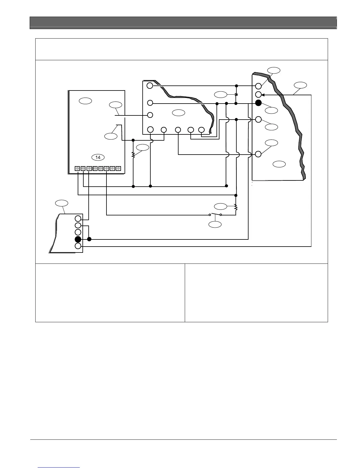
Figure 16: Wiring the Rothenbuhler 5110/4001-42 High Security Bell to the D9412GV2 or D7412GV2
Control Panel
1
2
3
4
RED ORG WHT BL K
N/O 1
COMM 1
N/C 1
X1 -
X1+
7
9
123 6
1
2
3
4
5
6
7
10
11
13
8
9
12
6
3
9
9
1 - 5110 Logic Board
2 - 4001-42 External Line Balancing Module
3 - D9412GV2 or D7412GV2 Control Panel
4 - Alarm output
5 - Alternate alarm
6 - Common
7 - +12 VDC
8 - Alarm zone input*
9 - 10 k
Ω
resistor
10 - Optional Silence switch
11 - D133 Relay Module
12 - BBL In 4
13 - BBL Out 5
14 - Terminal TB1
•
Use Terminal 11, 13, 14, 17, 19, 20, or 22. (Select only one.)
 Loading...


