D9412GV2/D7412GV2 | Operation and Installation Guide | Appendix A: System Wiring Diagrams, Issue A
70 Bosch Security Systems, Inc. | 7/09 | F01U003641-04
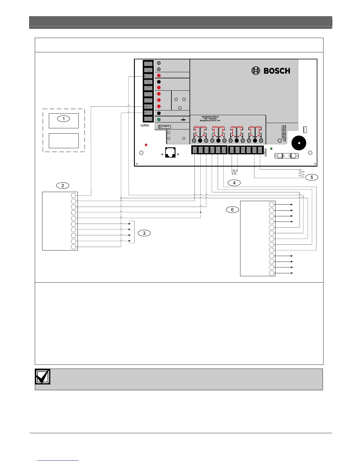
Figure 39: D9412GV2, Input Points and Peripheral Devices
P105BL
D125B
Sw. Aux Pwr
Zone B
Zone A
Pnl Common
Pnl Common
Loop B-
Loop A-
Loop B+
Loop A+
Earth Ground
10
9
5
4
3
8
2
1
7
6
D129
Aux Power
Zone B
Zone A
Common
Loop B-
Loop A-
Loop B+
Loop A+
Earth Ground
10
9
5
4
3
8
2
1
7
6
11
12
13
Loop A+
Loop A-
Loop B+
Loop B-
P105F
EARTH GROUND
COMMON
BATTERY NEGATIVE ONLY
Maximum Charging
Current 1.4 Amps.
BATTERY POSITIVE ONLY
RELAY A
RELAY B
RELAY C
+ AUX POWER
1
2
3
4
5
6
7
8
9
10
CLASS 2 TRANSFORMER
16.5 VAC 40 VA 60 Hz
Model D1640
Internally Fused - Do Not short
Requires Unswitched Outlet
Do Not Share With Other Equipment
GROUND FAULT DETECT
Enabled
Disabled
VOLTAGE RANGES
Open 3.7 - 5.0 VDC
Normal 2.0 - 3.0 VDC
Short 0.0 - 1.3 VDC
1211 13
Point 1 Point 2
1514 16
Point 3 Point 4
1817 19
Point 5 Point 6
2120 22
Point 7 Point 8
+
-
D130
PHONE
LED
RED
ON when
communicating
OFF when idle
PHONE LINE SEIZED
TIP
RING
TELCO
RING
TIP
PHONE LINE
SEIZED
TELCO CORD
MODEL D161
GRN
Point 8
S3 Option
Closed = 1K
Ω
EOL
Normal Operation
Open =AB-12 UL
Bell Box 220 K
Ω
D5200/D5360
PROG CONN
PROGRAMMABLE
ALARM OUTPUTS
Ter mi nal s
SWITCHED AUX
and
67
Ter minal
8
D9412GV2
1 - (Optional): For 24 V applications use a UL Listed
24 VDC power supply with a D130 Relay Module.
Refer to the D130 Installation Instructions (P/N:
74-06262-000) for correct wiring requirements.
2 - D130 Relay Module
3 - D125B Powered Loop Interface Module
4 - To UL Listed two-wire smoke detectors. Refer to
Two-Wire Smoke Detectors in the
D9412GV2/D7412GV2 Approved Applications
Compliance Guide (P/N: F01U003639) for a
listing of compatible two-wire smoke detectors.
5 - P105F 1 kΩ EOL resistor (P/N: 14-03130-004):
Suitable for non-powered initiating and
supervisory devices such as pull stations, heat
sensors, and valve tampers.
6 - P105BL1 1kΩ EOL resistor (P/N: 16179B): For
typical burglar alarm applications.
7 - D129 Dual Class A Initiation Circuit Module:
Provides optional Waterflow Alarm Retard
feature. Not suitable for two-wire smoke
detectors.
Use zero retard except for waterflow devices.
All external connections except Terminal 5 (battery positive) are power limited.
 Loading...


