D9412GV2/D7412GV2 | Operation and Installation Guide | 9.0 Off-Board Points
.
Bosch Security Systems, Inc. | 7/09 | F01U003641-04 41
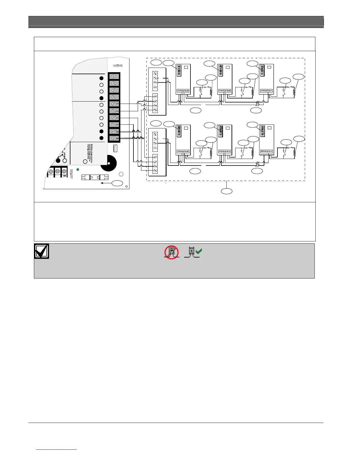
Figure 17: Connecting the D8125 POPEX to the D9412GV2 Control Panel
Reset Pin
Disable All Except Battery
Charging And Programming
PERIPHERAL DEVICE CONNECTIONS
RED POWER +
YELLOW DATA BUS A
GREEN DATA BUS B
BLACK COMMON
ZONEX OUT 1
ZONEX IN 1
N.F.P.A.
Style 3.5
Signaling
Line
Circuits
32
31
30
29
28
27
ZONEX OUT 2 26
25
ZONEX IN 2
ZONEX POWER +
24
ZONEX COMMON
23
21 22
(-)
(-)
(+)
(+)
AUX
IN
OUT
GND
(+)
(-)
D9127U/TD9127U/T
D9127U/T
(-)
(-)
(+)
(+)
AUX
IN
OUT
GND
(+)
(-)
D9127U/T
D9127U/T
D9127U/T
5
6
7
5
6
1
2
2 2
1
2
2
2
3
4
4
3
3
4
8
3
4
3
4
4
3
GRN
D5200/D5360
PROG CONN
Point 8
S3 Option
Closed = 1KΩ EOL
Normal Operation
Open =AB-12 UL
Bell Box 220 K
Ω
1 - D8125 POPEX Module
2 - Switch block
3 - D9127 Sensor Loop
4 - 33 kΩ EOL resistor (P/N: P106F (15-03130-002),
package of eight)
5 - Zone expansion loop
6 - Up to 119 POPITs
7 - On-board points
8 - Expansion zones
For system supervision, do not use looped wire terminals. Break the wire run to provide
supervision of the connections.
 Loading...


