D9412GV2/D7412GV2 | Operation and Installation Guide | 14.0 Faceplates
68 Bosch Security Systems, Inc. | 7/09 | F01U003641-04
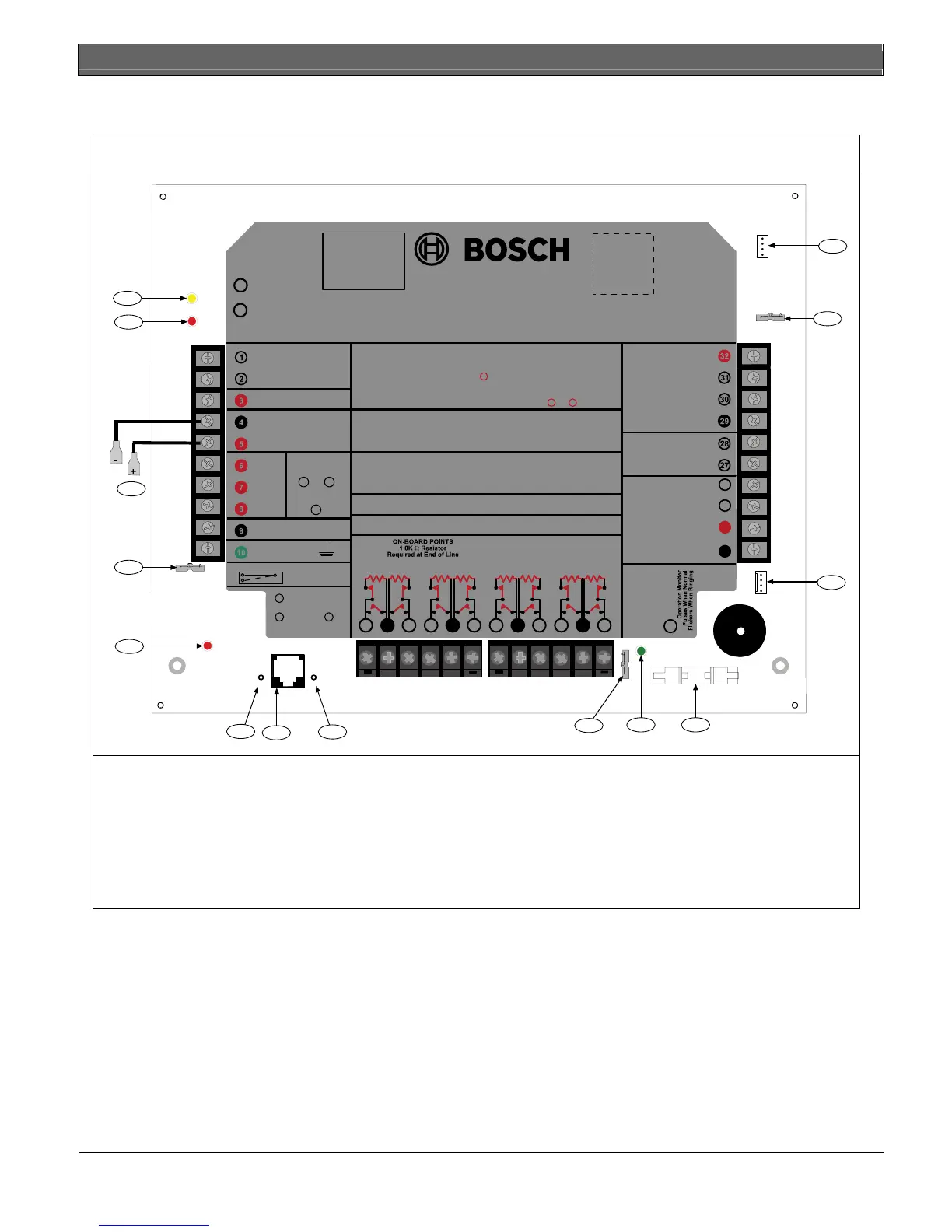
14.2 D7412GV2 Faceplate
Figure 37: D7412GV2 Faceplate
TELCO
RING
TIP
PHONE LINE
SEIZED
12
13
9
7
5
4
2
3
1
14
6
8
10 11
Refer to the
D9412GV2/D7412GV2 Approved Applications Compliance Guide
(P/N: F01U003639)
For System Wiring Diagram, Issue A and for Compatible Smoke Detectors
EARTH GROUND
COMMON
RELAY A
RELAY B
RELAY C
+ AUX POWER
CLASS 2 TRANSFORMER
16.5 VAC 40 VA 60 Hz
Model D1640
Internally Fused - Do Not short
Requires Unswitched Outlet
Do Not Share With Other Equipment
GROUND FAULT DETECT
Enabled
Disabled
Commercial Protected-Premises Control Panel
Refer to
D9412GV2/D7412GV2 Approved Applications Compliance Guide
(P/N: F01U003639)
For System Wiring Diagram, Issue A and for Compatible Smoke Detectors
D7412GV2 Control Panel is UL Listed for Central Station, Local, Auxiliary, Proprietary, and Household
Fire Alarm, and Central Station, Local, Police Station Connect, Household Burglar Alarm and
Encrypted Line Security when communicating via a network.
System is intended to be checked by a Qualified Technician at least every 3 years.
The types of initiating circuits for which the control panel has been approved are A, M, W, SS.
The types of signaling the control panel has been approved for are: DAC, OT, NC
VOLTAGE RANGES
Open 3.7 - 5.0 VDC
Normal 2.0 - 3.0 VDC
Short 0.0 - 1.3 VDC
Reset Pin
Disable All Except Battery
Charging And Programming
PERIPHERAL DEVICE CONNECTIONS
RED POWER +
YELLOW DATA BUS A
GREEN DATA BUS B
BLACK COMMON
ZONEX OUT 1
ZONEX IN 1
N.F.P.A.
Style 4.0
Signaling
Line
Circuits
F01U003799-01
1211 13
Point 1
Point 2
1514 16
Point 3
Point 4
1817 19
Point 5
Point 6
2120 22
Point 7
Point 8
LEDs Off When Normal
Charging Status
Low Battery - 12.1 VDC
YEL
RED
10.2 VDC - Battery Load Shed
This equipment should be installed in accordance with the NFPA 70 (National Electrical Code)
and NFPA 72 (National Fire Alarm Code) for Local, Central Station, Proprietary and Household Fire
Warning Systems and under the limits of the Local Authority Having Jurisdiction (National Fire
Protection Association, Battermarch Park, Quincy, MA 02269). Printed information describing
proper installation, operation, testing, maintenance, evacuation planning and repair service is to
be provided with this equipment.
NOT USED
26
25
NOT USED
ZONEX POWER +
24
ZONEX COMMON
23
SDI Connector
BATTERY NEGATIVE ONLY
BATTERY POSITIVE ONLY
CAUTION: See
D9412GV2/D7412GV2 Operation and Installation Guide
WARNING!
Multi-Battery installation requires
Model D122/D122L Dual Battery
Harness. Improper installation can
be a fire hazard.
Battery: Replace every 3 to
5 years with one or two Model
D126 or D1218 12V Lead Acid
Batteries.
GRN
Point 8
S3 Option
Closed = 1KΩ EOL
Normal Operation
Open =AB-12 UL
Bell Box 220 KΩ
D5200/D5360
PROG CONN
D7412GV2
CAUTION:
Avoid damage to Panel.
Do not connect 24 V to terminals.
Maximum charging current 1.4 A
PHONE
LED
RED
ON when
communicating
OFF when idle
PHONE LINE SEIZED
TIP
RING
TELCO CORD
MODEL D161
PROGRAMMABLE
ALARM OUTPUTS
Terminals
SWITCHED AUX
and
67
Terminal
8
POWER SUPPLY REQUIREMENTS
The Power Supply provides a maximum of 1.4 Amps for the Control Panel and all
Accessory Devices. For System Loading, refer to
D9412GV2/D7412GV2
Operation and Installation Guide
(P/N: F01U003641).
(P/N: F01U003641) for Power Requirements relating to Terminals 6 and 7 .
All external connections except Terminal 5 (battery positive) are inherently power
limited. Requirements for battery standby time might reduce allowable output.
Minimum system requirements for Classification in accordance with ANSI/SIA CP-01-2000:
UL Listed and Classified control unit Model D9412GV2, D7412GV2, or D7212GV2;
UL Listed and Classified keypad Model D1256, D1257, D1260, D1255, D1255R, or D1255RW;
UL Listed Local Bell
Incorrect wiring will
damage this equipment.
Suitable for dry indoor
use only.
Devices powered by the
AUX power output must
be supervised.
1 - Charging status LED (yellow)
2 - Low battery LED (red)
3 - Color-coded battery leads
4 - Ground fault detect enable
5- Phone LED (red)
6 - Tip
7 Telephone cord connector
8- Ring
9- S3, Point 8 EOL selection
10- Operation monitor LED (green)
11- Accessory connector
12- Programming connector
13- Reset pin
14- SDI quick connector
 Loading...


