D8128D
Installation
D8128D Installation Guide
41343F Page 10 © 2004 Bosch Security Systems, Inc.
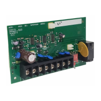
3.3.2 Connecting the D8128D to the Control Panel using Molex Connectors
Each D8128D module is supplied with a 12-inch (30 cm) female-to-female Molex cable assembly.
P1 and P2 are Molex connectors that parallel the COM, IN, OUT and +12 VDC terminals on the terminal strip. In
installations where there are multiple D8128Ds in use, use these connectors (as opposed to terminals) with the supplied
cable. However, when connecting D8128D modules directly to the panel, the terminal strip may be easier to use.
The Molex connectors provided are “keyed.” (molex plug can only fit in one direction). However, to be sure the
connector is attached correctly, be sure the red wire is on the bottom of P1 (or P2) and the black wire is on the top.
When connecting multiple D8128Ds to a control panel, you may connect the control panel terminals to P1 or the Com,
In, Out, and +12V terminals on the first D8128D and then connect P2 of the first D8128D to P1 of the second D8128D
and so on.
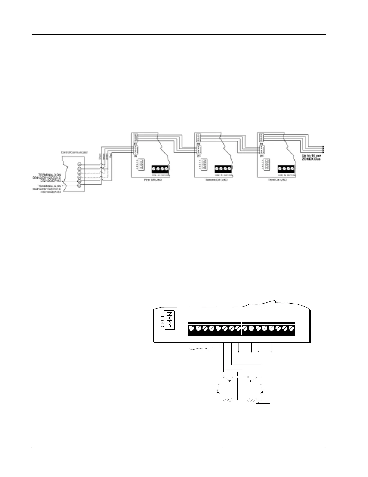
Figure 6: Wiring Multiple D8128Ds using Molex Connectors
3.4 Wiring OctoPOPIT Sensor Loops
3.4.1 OctoPOPIT Sensor Loops
Only the resistance on the loop limits the number of normally-open and/or normally-closed detection devices each
sensor loop can supervise. Resistance on each sensor loop must be less than 100 Ω with the detection devices connected.
Certain UL and NFPA applications may limit the number of detection devices. Consult the appropriate UL or NFPA
standards.
The OctoPOPIT detects open, short, normal, and grounded circuit conditions on its sensor loops and transmits the
conditions to the panel. Each sensor loop is assigned a point number and transmits to the panel separately.
Bosch Security Systems recommends you use twisted-pair wire for the OctoPOPIT sensor loops to avoid EMI problems.
Run wires away from the premises telephone and AC wiring. If you suspect a noisy environment, use shielded cable.
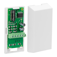
There are two rows of terminal numbers
on the OctoPOPIT. In the row closest to
the terminal blocks, the positive outputs
for the sensor loops are labeled P1 to P8.
Sensor loop outputs P1 and P2, P3 and
P4, P5 and P6, and P7 and P8 share
common terminals. The common
terminals for each pair are labeled COM.
Terminate each OctoPOPIT sensor loop
with a 1 kΩ end-of-line resistor. Attach a
resistor even if you don’t enable the loop.
The OctoPOPIT comes with a D105BL
resistor for each sensor loop.
TO PANEL
TO ADDITIONAL OCTOPOPIT
SENSOR LOOPS
OCTOPOPIT
SENSOR LOOPS
1 k
Ω
EOL RESISTOR
(P105BL, 15-03130-004)
COM
IN OUT+12V P1 COM P2 P3 COM P4 P5 COM P6 P7 COM P8
D8128D OctoPOPIT
Figure 7: D8128D OctoPOPIT Sensor Loops
Do not to duplicate point assignments. Points do not function properly if assigned to both an OctoPOPIT sensor loop
and a POPIT, to two OctoPOPIT sensor loops, or to two POPITs.
 Loading...