D8128D
Installation
D8128D Installation Guide
© 2004 Bosch Security Systems, Inc. Page 7 41343F
3.0 Installation
Before installing the D8128D OctoPOPIT, become familiar with the Operation and Installation Guide and the Program
Entry Guide corresponding to your system. Bosch Security Systems recommends the following four-step process for the
most effective installation:
1. setting the OctoPOPIT switches,
2. physically mounting the OctoPOPIT to the enclosure,
3. wiring the OctoPOPIT, and
4. wiring OctoPOPIT sensor loops.
Each step is explained more fully in this chapter.
3.1 Setting OctoPOPIT Switches
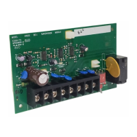
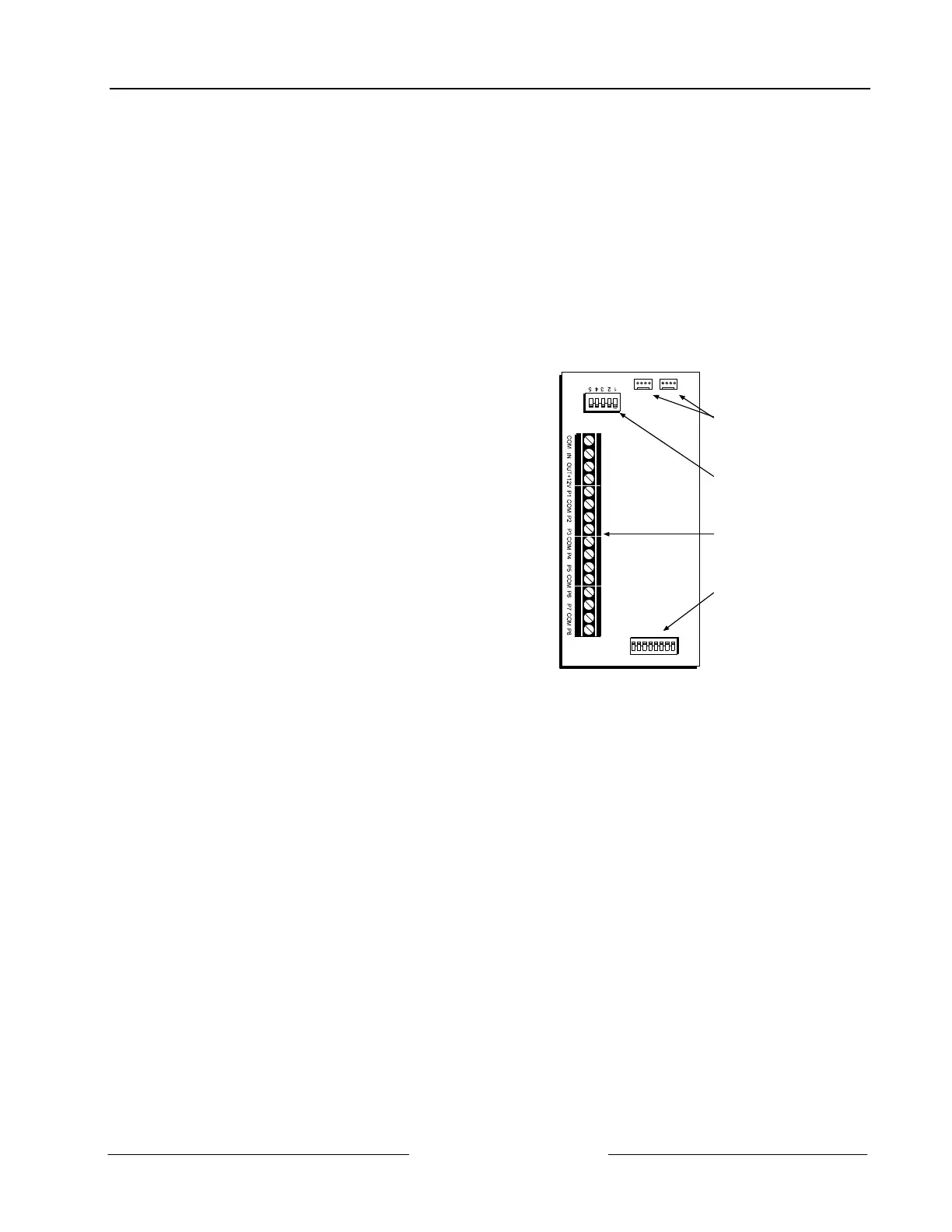
The D8128D OctoPOPIT has two sets of DIP switches. The DIP
switches on the top of the unit (with the terminal strip along
the left edge) are used to set the OctoPOPIT’s address. The DIP
switches at the bottom of the unit are used to enable or disable
individual points connected to the OctoPOPIT.
3.1.1 Address Switches
The switches on the D8128D OctoPOPIT set point assignments
and line termination (see Figure 3). These switches are easier to
set before mounting the D8128D in the enclosure.
3.1.1.1 Address Assignment Switches
Switches 1, 2, 3, and 4 assign the OctoPOPIT sensor loops to
point numbers on the panel. Table 7 through Table 10 show the
OctoPOPIT switch settings for point assignments, depending
on the control panel being used.
23451 678
P O I N T S
Molex Connectors
Address Dipswitches
Terminal Strip
Point Dipswitches
Figure 3: D8128D OctoPOPIT Layout
3.1.1.2 Line Termination Switch Settings
Switch 5 sets line termination.
• If there is no D8125 POPEX module connected to ZONEX 1, set switch 5 of only one D8128D connected to
those terminals to the ON position.
• If there is a D8125 POPEX module connected to ZONEX 1, set switch 5 of all D8128Ds connected to those
terminals to the OFF position.
• If there is no D8125 POPEX module connected to ZONEX 2, set switch 5 of only one D8128D connected to
those terminals to the ON position.
• If there is a D8125 POPEX module connected to ZONEX 2, set switch 5 of all D8128Ds connected to those
terminals to the OFF position.
3.1.2 Point DIP Switches
Each point connected to the D8128D is enabled or disable by turning its respective DIP switch to the closed or open
position, respectively. For example, to disable a device connected to the P3 terminal (Point 3), move DIP switch number
3 to the OPEN position.
Use the point DIP switches to disable conflicting points, such as when a D9210B Access Control module must be assigned
to a point that falls within the range of the D8128D OctoPOPIT. In this example, a D9210B is assigned to Point 20. On
the same system, a D8128D OctoPOPIT is assigned to Points 17 through 24. Moving the DIP switch for Point 4 to the
OFF position would effectively disable Point 20, allowing normal operation of the D9210B and the OctoPOPIT.
Terminate each OctoPOPIT sensor loop with a 1 kΩ end-of-line resistor. Attach a resistor even if you don’t enable the
loop.
 Loading...