D8128D
Installation
D8128D Installation Guide
41343F Page 8 © 2004 Bosch Security Systems, Inc.
3.2 Mounting the OctoPOPIT
The D8128D OctoPOPIT Module can be installed in the enclosure with the panel using standard four-conductor 22
AWG (0.8 mm) wire, or in a separate enclosure (model D8103, D8108A, or D8109) up to 200 ft. (61 m) from the panel
using shielded (recommended) standard four-conductor 22 AWG (0.8 mm) wire. Refer to the Cabling Specifications in
Section 2.1 when using the D125B or the D129.
For UL Listed systems, mount the D8128D in a tamper-proof enclosure.
To install OctoPOPITs in the panel’s
enclosure, complete the following
procedure. Use the D137 Mounting
Bracket to install OctoPOPITs in
enclosures with no module-mounting
locations available.
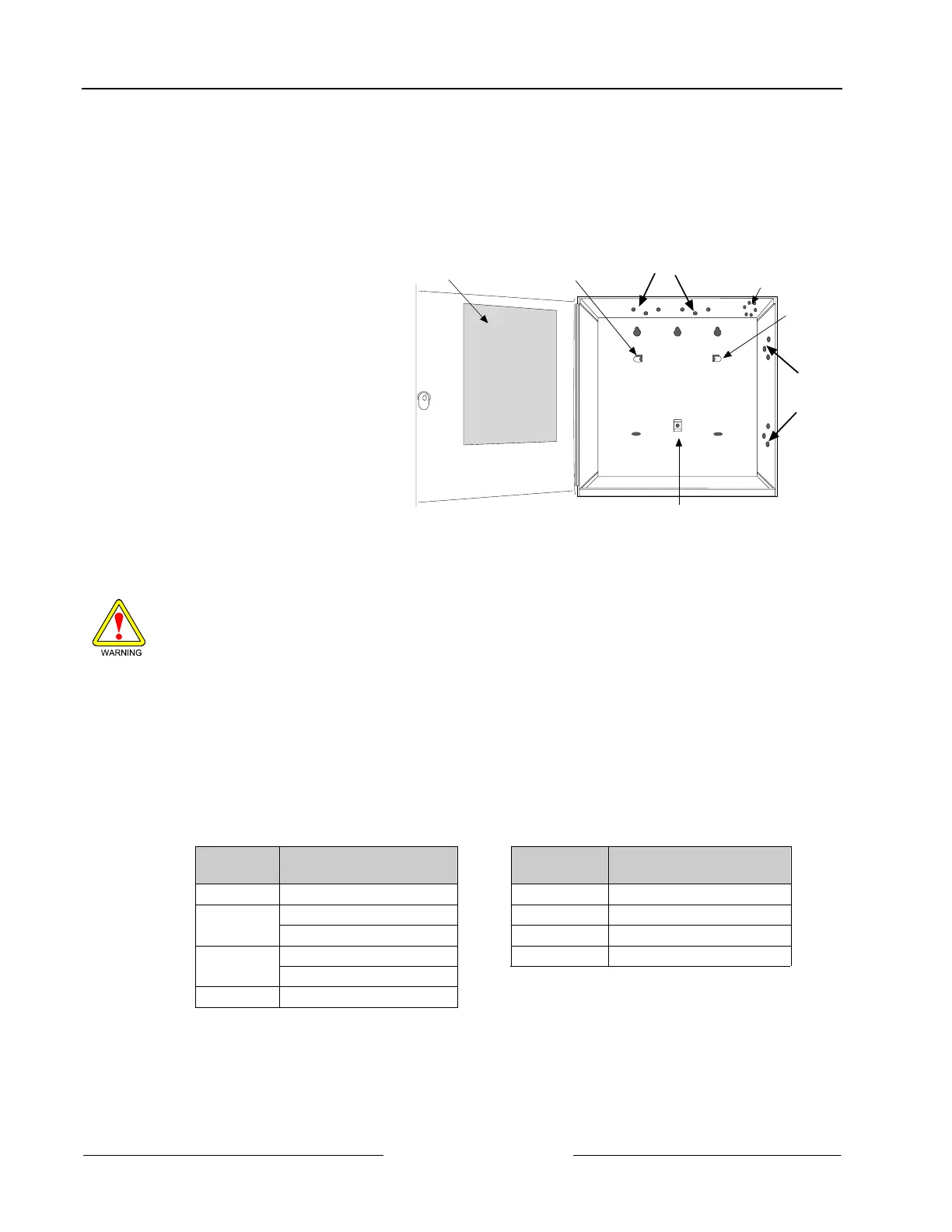
1. Align the OctoPOPIT module
with any of the four mounting
locations in the enclosure (refer to
Figure 4).
2. Use the screws provided with the
module to secure it in the
enclosure.
POINT CHART LABEL
MOUNTING
SKIRT HOOK
MODULE MOUNTING
LOCATIONS
MODULE
MOUNTING
LOCATIONS
TAMPER SWITCH
MOUNTING LOCATION
MOUNTING
SKIRT HOOK
SKIRT MOUNTING HOLE
Figure 4: Mounting Enclosure
3.3 Wiring the OctoPOPIT
Disconnect all power to the control panel before beginning any work with the internal components. Serious
injury could result from electrical shock.
Power down the panel by disconnecting the positive (red) battery lead at the battery and unplugging the transformer.
The D8128D can be installed up to 200 ft. (61 m) from the control panel. There are two methods for connecting the
D8128D to a control panel: wire the OctoPOPIT to the control panel using the terminal strip on the side of the module
or connect using the Molex connectors (P1 and P2).
AC INDUCTION: Avoid installing ZONEX data wires and ZONEX input (sensor loop) wires around any AC
conduit/wiring or electrical devices that emit fields of electromagnetic interference (EMI).
3.3.1 Connecting the D8128D to the Control Panel using the Terminal Strip
When connecting the D8128D to the control panel via the OctoPOPIT’s terminal strip, the following connections must
be made:
D8128D D9412G/D9412/D9112/
D9112B1/D9124
D8128D D7412G/D7412/D7212G/
D7212B1/D7212
Common Terminal 23 Common Terminal 9
Out Zonex 1 = Terminal 27 Out Terminal 27
Zonex 2 = Terminal 25 In Terminal 28
In Zonex 1 = Terminal 28 +12 V Terminal 3
Zonex 2= Terminal 26
+12 V Terminal 24
Table 6: Terminal Strip Connections
 Loading...