EN | 13
D9412G/D7412G | Operation & Installation Guide |
Bosch Security Systems | 10/03 | 43488E
2.0 Overview
2.2.1 Compatible Accessories
See the Bosch Security Systems Product Catalog for
additional information.
2.3 New Features in D9412G/D7412G
2.3.1 Introduction
Eventually, the D9412G will replace the D9412 and
D9112, and the D7412G will replace the D7412 and
D7212. The suffix “G” indicates the control panel’s
ability to detect ground fault conditions. All other
software feature sets that were available in the 9000
Series Control Panels remain the same as in the
D9412G/D7412G.
2.3.2 Ground Fault Detect
For the D9412G/D7412G to detect ground fault
conditions, the Earth Ground Terminal on the control
panels were electrically isolated from all other
terminals. A Ground Fault Detect Enable switch (S4)
was added to the panel and is located just under
Terminal 10, Earth Ground. See Section 3.5.2 Ground
Fault Detect Enable for information on operating this
function.
2.3.3 Added Feature When Using Ground Fault
Detect
When Ground Fault Detect is enabled (S4 closed), Points
1 to 8 can be used for non-powered fire-initiating
devices such as heat detectors, 4-wire smoke detectors,
pull stations, and so on. A D125B Powered Loop
Interface or a D129 Dual Class A Interface Module is no
longer required when connecting the non-powered
fire-initiating devices to Points 1 to 8.
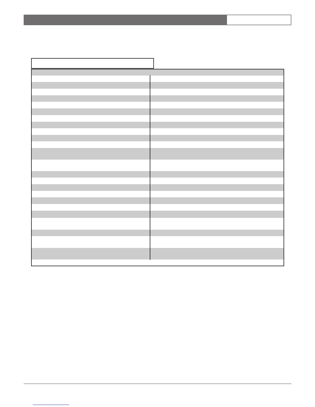
Table 6: Compatible Accessories
Model Title Model Title
D122 Dual Battery Harness D1257 Fire Annunciator
D125B Powered Loop Interface Module D1260 Alpha V Command Center
D127 Reversing Relay D1640 16.5 VAC 40 VA Transformer
D129 Dual Class A Initiation Circuit Module D5500 Remote Account Manager IV
D130 Relay Module D8004 Transformer Enclosure
D136 Plug-In Relay D8124A, D8122 Derived Channel STU
D161 Phone Cord D8125 POPEX Module
D162 Phone Cord D8125MUX Multiplex Bus Interface
D185 Reverse Polarity Module D8125INV* Wireless Interface Module
D192C/D192G Bell Circuit Supervision Module D8128D OctoPOPIT Module
D268/D269 Independent Zone Control (On-Board
and OctoPOPIT Points)
D8129 OctoRelay Module
D279A Independent Zone Control (On-Board
and OctoPOPIT Points)
D8130 Release Module
D442 Bells (4 cm/10 in.) D8132 Battery Charger Module
D448/D449 Mini-Horns D9002-5 Accessory Module Mounting Skirt
D720 Command Center (Area LED) D9127U/T POPIT Module
D720R LED Command Center (red) D9131A Parallel Printer Interface Module
D720W LED Command Center (white) D9210B Access Control Interface Module
D928 Dual Phone Line Switcher ZX776Z PIR Motion Sensor (15 m/50 ft.) with POPIT
D1218 12 V, 17.2 Ah Rechargeable Battery ZX794Z PIR Motion Sensor (24 m/80 ft.) with POPIT
D1255 Command Center (General Purpose) ZX865
PIR/Microwave Motion Sensor (1.7
°
C/35
°
F)
with POPIT
D1255R LED Command Center (red) ZX938Z PIR Motion Sensor (18 m/60 ft.) with POPIT
D1255RW LED Command Center (white) ZX970
PIR/Microwave Motion Sensor (1.7
°
C/35
°
F)
with POPIT
D1256 Fire Command Center *
The D8125INV has not been investigated by UL. Not to be
used in UL Listed installations.

 Loading...


