Bosch Security Systems | 10/03 | 43488E
EN | 52
D9412G/D7412G | Operation & Installation Guide |
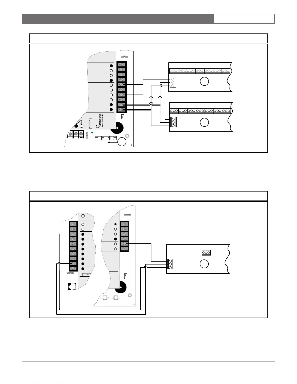
Figure 24: D811 Module Wiring to the D9412G
GRN
Reset Pin
Disable All Except Battery
Charging And Programming
PERIPHERAL DEVICE CONNECTIONS
RED POWER +
YELLOW DATA BUS A
GREEN DATA BUS B
BLACK COMMON
ZONEX OUT 1
ZONEX IN 1
N.F.P.A.
Style 3.5
Signaling
Line
Circuits
32
31
30
29
28
27
PROG
CONN
Point 8
GND FAULT
Detect
E
N
A
B
L
E
D
I
S
A
B
L
E
ZONEX OUT 2
26
25
ZONEX IN 2
ZONEX POWER +
24
ZONEX COMMON
23
21 22
1
3
2
1234567 8
GND
AUX
DATA
1234567 8
GND
AUX
DATA
1 - D811 for relay number 53
2 - D811 for relay number 117
3 - On-board points
Figure 25: D811 Module Wiring to the D7412G
5
GND
AUX
DATA
EARTH GRO
COMMON
BATTERY N
Maximum Charging
Current 1.4 Amps.
BATTERY POSITIVE ONLY
RELAY A
RELAY B
RELAY C
+ AUX PO
1
2
3
4
5
6
7
8
9
10
CLASS 2 TRANS
16.5 VAC 40 VAC
Part No. D1640
Internally Fuse
Requires Unsw
Do Not Share
Low Battery
RED
PR
AL
Re
GROUND FAUL
Pin
Battery
amming
E CONNECTIONS
POWER +
DATA BUS A
DATA BUS B
COMM ON
ZONEX OUT 1
ZONEX IN 1
32
31
30
29
28
27
PROG
CONN
1
1 - D811 for relay number 53
9.0 Off-Board Relays

 Loading...


