Bosch Security Systems | 10/03 | 43488E
EN | 22
D9412G/D7412G | Operation & Installation Guide |
4.2.3 Replacing the Battery
Replace batteries every 3 to 5 years under normal use.
Record the date of installation directly on the battery.
Exceeding the maximum output ratings or
installing the transformer in an outlet that is
routinely switched off causes heavy discharges.
Routine heavy discharges can lead to premature
battery failure.
D8132 Boost Battery Backup:
Adding a D8132 Battery
Charger Module supports additional batteries of up to
27 Ah capacity, if required.
The D8132 Battery Charger Module can be used to
connect two additional batteries for a total of four. The
4.0 Power Supply
panel plus any connected D8132 Modules and AUX
power supplies must be on the same AC circuit to
discharge evenly if AC power fails. The number of
D8132 Modules is determined by the number of
available outlets on the same circuit. Refer to the
Standby Battery and Current Rating Chart in the
D9412G/D7412G Approved Applications Compliance Guide
for battery standby time calculations.
In applications where the supervision of two
batteries is required by the AHJ, use a D113
Battery Supervision Module.
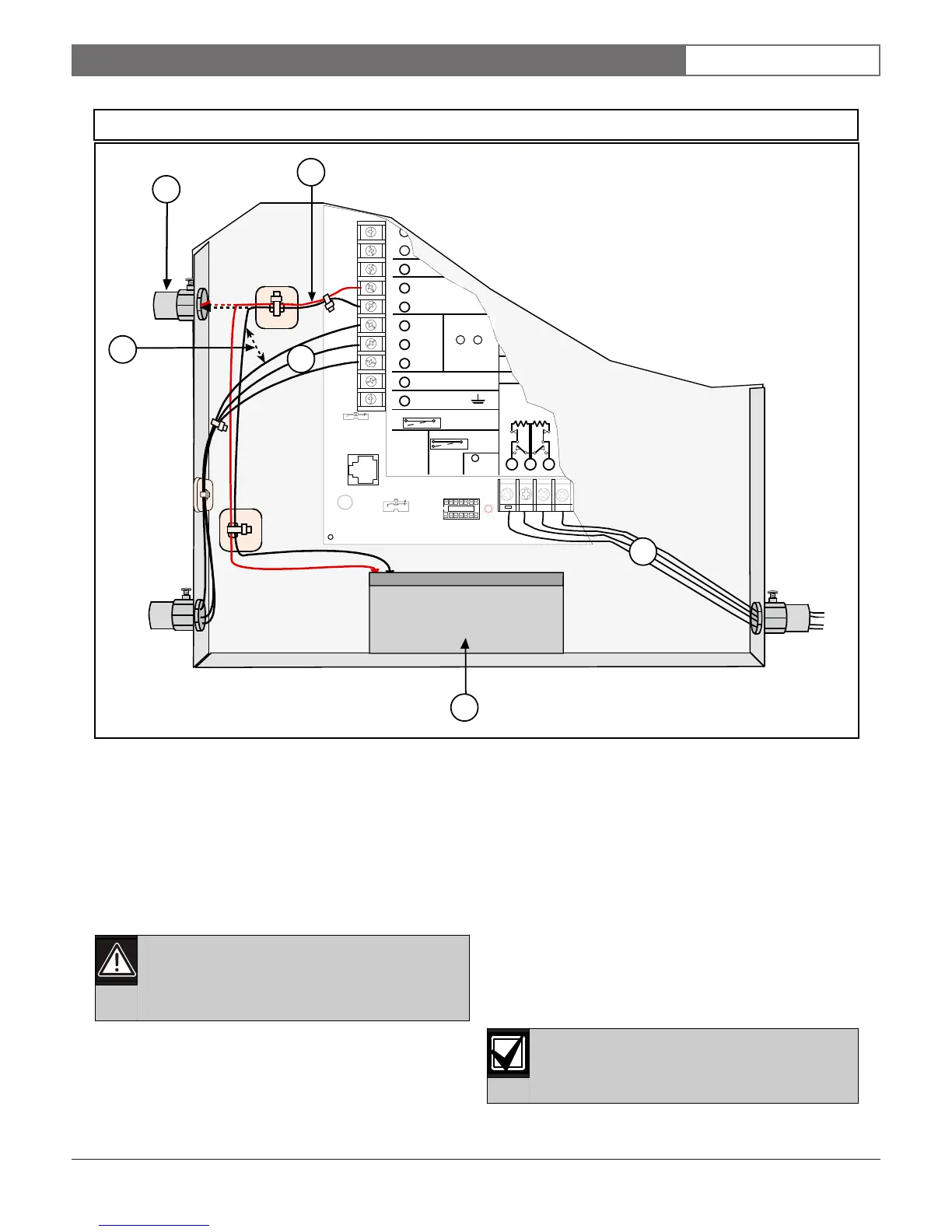
4 - Option wires
5 - Output or zone wires
6 - Standby battery
EARTH GROUND
COMMON
BATTERY NEGATI
Maximum Charging
Current 1.4 Amps.
BATTERY POSITIVE ONLY
RELAY A
RELAY B
RELAY C
+ AUX
1
2
3
4
5
6
7
8
9
10
D
PROGRAMMABLE
ALARM OUTPUTS
Termin als
Requires Optional
D136 Relay
In ALT ALARM
& SW AUX
&
78
GROUND FAULT DETECT
Enabled
Disabled
PHONE
LED
RED
ON WHEN
COMMUNICATING
OFF WHEN IDLE
LOOP START
GND START
GROUND START
1211 13
Point 1
Point 2
GROUND START
Requires
Relay # D136 in
Ground
Start Socket
6
3
2
4
1
5
Figure 5: Non-Power Limited Wiring
1 - Only required if external batteries are used.
2 - Battery wires
3 - 6.4 mm (0.25 in.) minimum. To ensure proper
spacing, secure wires using Tie-Wraps or
similiar devices.

 Loading...


