Bosch Security Systems | 10/03 | 43488E
EN | 44
D9412G/D7412G | Operation & Installation Guide |
8.4.4 Setting the OctoPOPIT Switches
The D8128D OctoPOPIT has two sets of DIP switches
(see Figure 14). The DIP switches on the top of the unit
(with the terminal strip along the left edge) are used to
the set the OctoPOPIT’s address. The DIP switches at
the bottom of the unit are used to enable or disable
individual points connected to the OctoPOPIT.
Address Switches
The switches on the D8128D OctoPOPIT set point
assignments and line termination. These switches are
easier to set before mounting the D8128D in the
enclosure.
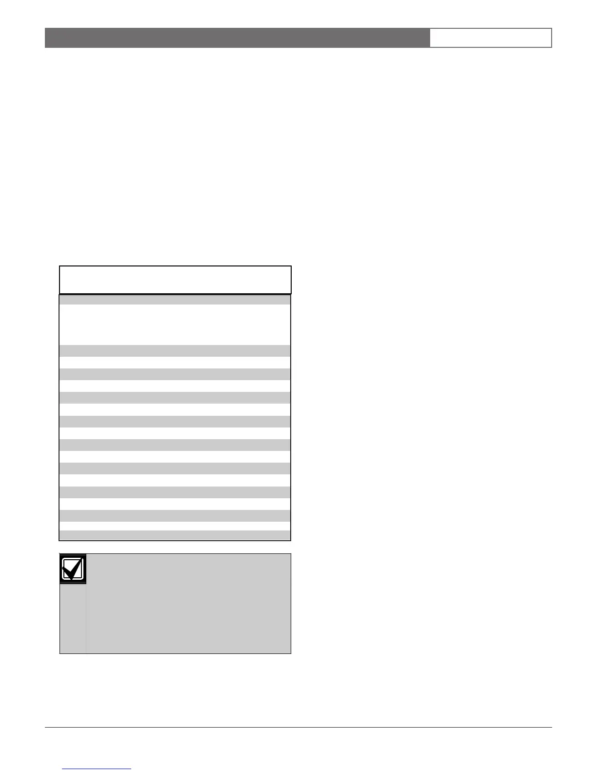
Switches 1, 2, 3, and 4 assign the OctoPOPIT sensor
loops to point numbers on the panel. Table 13 shows the
OctoPOPIT switch settings for point assignments.
Switch 5 sets line termination.
• If there is no D8125 POPEX Module connected
to ZONEX 1, set switch 5 of only one D8128D
connected to those terminals to the ON position.
• If there is a D8125 POPEX Module connected to
ZONEX 1, set switch 5 of all D8128Ds connected
to those terminals to the OFF position.
• If there is no D8125 POPEX Module connected
to ZONEX 2, set switch 5 of only one D8128D
connected to those terminals to the ON position.
• If there is a D8125 POPEX Module connected to
ZONEX 2, set switch 5 of all D8128Ds connected
to those terminals to the OFF position.
Point DIP Switches
Each point connected to the D8128D is enabled or
disabled by turning its respective DIP switch to the
closed or open position, respectively. For example, to
disable a device connected to the P3 Terminal (Point 3),
move DIP switch number 3 to the OPEN position.
Use the point DIP switches to disable conflicting points,
such as when a D9210B Access Control Module must be
assigned to a point that falls within the range of the
D8128D OctoPOPIT. In this example, a D9210B is
assigned to Point 20. On the same system, a D8128D
OctoPOPIT is assigned to Points 17 through 24.
Moving the DIP switch for Point 4 to the OFF position
would effectively disable Point 20, allowing normal
operation of the D9210B and the OctoPOPIT.
Terminate each OctoPOPIT sensor loop with a 1 kΩ
EOL resistor. Attach a resistor even if you don’t enable
the loop.
8.4.5 Mounting
The D8128D OctoPOPIT Module can be installed in
the enclosure with the panel using standard four-
conductor 0.8 mm (22 AWG) wire, or in a separate
enclosure (Model D8103, D8103A, or D8109) up to 61 m
(200 ft.) from the panel using shielded (recommended)
standard four-conductor 0.8 mm (22 AWG) wire. If
using the D125B or D129, refer to the Specifications
section of the D8128D Installation Guide for cabling
requirements.
For UL Listed systems, mount the D8128D in a tamper-
proof enclosure.
To install OctoPOPITs in the panel’s enclosure,
complete the following procedure. Use the D137
Mounting Bracket to install OctoPOPITs in enclosures
with no module-mounting locations available.
1. Align the OctoPOPIT module using any of the four
mounting locations in the enclosure (refer to Figure
2).
2. Use the screws provided with the module to secure it
in the enclosure.
8.0 Off-Board Points
For the D8128D OctoPOPITs assigned to
Points 121 to 127, 241, and 247, set Point
Input Switch 8 to the OPEN position.
D9412G uses Points 9 to 127 on ZONEX 1
and Points 129 to 247 on ZONEX 2.
D7412G uses Points 9 to 75 on ZONEX 1
only.
ZONEX 1
D8128D Address Switches ZONEX 2
Points 9
to 127
1 2 3 4 5 Points
129 to
247
9 to 16 ON ON ON ON * 129 to 136
17 to 24 ON ON ON OFF * 137 to 144
25 to 32 ON ON OFF ON * 145 to 152
33 to 40 ON ON OFF OFF * 153 to 160
41 to 48 ON OFF ON ON * 161 to 168
49 to 56 ON OFF ON OFF * 169 to 176
57 to 64 ON OFF OFF ON * 177 to 184
65 to 72 ON OFF OFF OFF * 185 to 192
73 to 80 OFF ON ON ON * 193 to 200
81 to 88 OFF ON ON OFF * 201 to 208
89 to 96 OFF ON OFF ON * 209 to 216
97 to 104 OFF ON OFF OFF * 217 to 224
105 to 112 OFF OFF ON ON * 225 to 232
113 to 120 OFF OFF ON OFF * 233 to 240
121 to 127 OFF OFF OFF ON * 241 to 247
*
Line Termination Switch
Table 13: D8128D OctoPOPIT Switch Settings for
D8412G/D7412G

 Loading...


