Bosch Security Systems | 10/03 | 43488E
EN | 74
D9412G/D7412G | Operation & Installation Guide |
Index
F
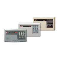
Faceplates
D7412G ................................................................................... 64
D9412G ................................................................................... 63
FCC
Registration Number .......................................................... 27
FCC Rules .................................................................................... 9
Fire System Power Formula ............................................ 25, 26
G
Ground Fault ....................................................................... 13, 18
Detect ............................................................................... 13, 18
Ground Start ...................................................................... 19, 29
I
Installation................................................................................... 17
Enclosure Options ................................................................ 17
Installing the Assembly ............................................................18
K
Keyswitch.................................................................................... 53
Standard Features.................................................................15
L
LEDs
AC Power Status................................................................... 31
Charging Status ...................................................... 20, 23, 24
Communication Failure ....................................................... 31
D928 Status ............................................................................ 31
Low Battery ................................................................... 23, 24
Operation Monitor ....................................................... 23, 28
Phone Line Status................................................................. 31
Listings and Approvals .............................................................16
N
NetCom Functionality ..............................................................14
Network Interface Module ..................................................... 58
Networks
Ethernet ................................................................................. 58
New Features .............................................................................13
Notes, Cautions and Warnings ................................................ 8
O
OctoPOPITS
Mounting................................................................................ 44
OctoPOPITs......................................................................... 19, 43
Testing ..................................................................................... 48
Wiring ..................................................................................... 45
OctoRelays .......................................................................... 19, 49
Wiring ......................................................................................51
Off-board Points ................................................................ 14, 37
Off-board Relays ...................................................................... 49
On-board Points ..........................................................14, 19, 33
P
Phone .......................................................................................... 27
Phone Cords ........................................................................ 27, 30
Phone Lines ........................................................................ 19, 27
Dialing Format ...................................................................... 28
Dual Phone Line Switcher ................................................. 29
Ground Start ........................................................................ 29
Jacks ..................................................................................14, 27
Phone Line Monitor ............................................................ 28
Rng Indicator ........................................................................ 28
Seizure ..............................................................................14, 27
Status LED ............................................................................. 31
Point Address Charts
ZONEX 1................................................................................ 71
ZONEX 2............................................................................... 72
Point Chart Label ..................................................................... 20
Installing................................................................................. 20
Points ............................................................................................14
Off-board .........................................................................14, 37
On-board .................................................................. 14, 19, 33
Sensor Loops........................................................................ 33
Standard Features.................................................................14
POPEX ................................................................................. 19, 37
Wiring ..................................................................................... 38
POPITs .................................................................................. 37, 38
Testing ..................................................................................... 48
Wiring ...............................................................................19, 38
Power
AC Power Status LED ........................................................ 31
Auxiliary................................................................................. 25
Continuous Current Draw ................................................ 25
Primary .................................................................................... 21
Programmable Terminals .................................................... 25
Secondary ............................................................................... 21
Total Available ....................................................................... 25
Power Failure .............................................................................21
Power Module
Battery Discharge Schedule ............................................... 23
Charging Status LED .......................................................... 24
Replacing Batteries .............................................................. 22
Power Outputs
Alarm ...................................................................................... 25
Alternate Alarm.................................................................... 25
Auxiliary................................................................................. 25
Circuit Protection ................................................................. 25
Continuous Power Outputs Terminals ............................ 25
Fire System Power Formula .............................................. 26
Programmable....................................................................... 25
Programmable Power Outputs Terminals ....................... 25
Switched Auxiliary ............................................................... 25
Total Available Power .......................................................... 25
ZONEX .................................................................................. 25
Power Supply .............................................................................21
Primary Power Terminals .........................................................21
Printer ......................................................................................... 57
Programmer ............................................................................... 20
Connecting..............................................................................61
Programmer Connector ...........................................................61
Programming
Standard Features.................................................................15
Programming the Panel ........................................................... 20

 Loading...