Service Manual Bosch IDS 2.0 | 33
Bosch Thermotechnology Corp. | 07.2021
Data subject to change
11 Field Settings
11.1 Initial Unit Preparation and Installation Checklist
WARNING:
This checklist is NOT to be used in place of the Installation,
Operation, and Maintenance Manual.. Please refer to
Installation, Operation, and Maintenance Manual for
specifications and detailed installation requirements.
No. Setting Up the Unit
1 Be sure to consider maximum lineset lengths
2
Ensure proper clearances and location restrictions for
outdoor and indoor unit
3 Ensure outdoor unit is installed on a pad
No. Check Refrigerant Lines
1 Ensure proper lineset diameters
2 Ensure proper insulation and routing
3 Braze refrigerant lines using proper techniques
4 Perform leak check
5 Properly evacuate lines
6 Open service valves, ensure they are fully open
No. Low Voltage Wiring
1 Ensure low voltage wiring does not exceed maximum length
2 Ensure proper gage wire is used
3
Connect thermostat wiring as shown in wiring diagrams in
IOM
No. High Voltage Wiring
1
Connect high voltage power supply ensuring proper safety
precautions are followed
2 Install high voltage disconnect switch
3 Ensure proper grounding on indoor and outdoor units
Table 22
11.2 Initial Start-up Checklist
WARNING:
This checklist is NOT to be used in place of the Installation,
Operation, and Maintenance Manual. Please refer to
Installation, Operation, and Maintenance Manual for
specifications and detailed installation requirements.
No. System Start-up
1
Consider non-default dipswitch positions as needed, refer to
section 11.3.2 and 11.3.4
2 Set thermostat to OFF prior to unit charging
No. Unit Charging
1
Determine proper charging method: weigh in method or
charge by subcooling. If design superheat and subcooling
cannot be achieved, refer to section 13.9 for troubleshooting.
2
After 20 minutes of unit operation, ensure proper drainage of
condensate on indoor and outdoor units
3 Force unit into Manual Defrost to verify functionality.
Table 23
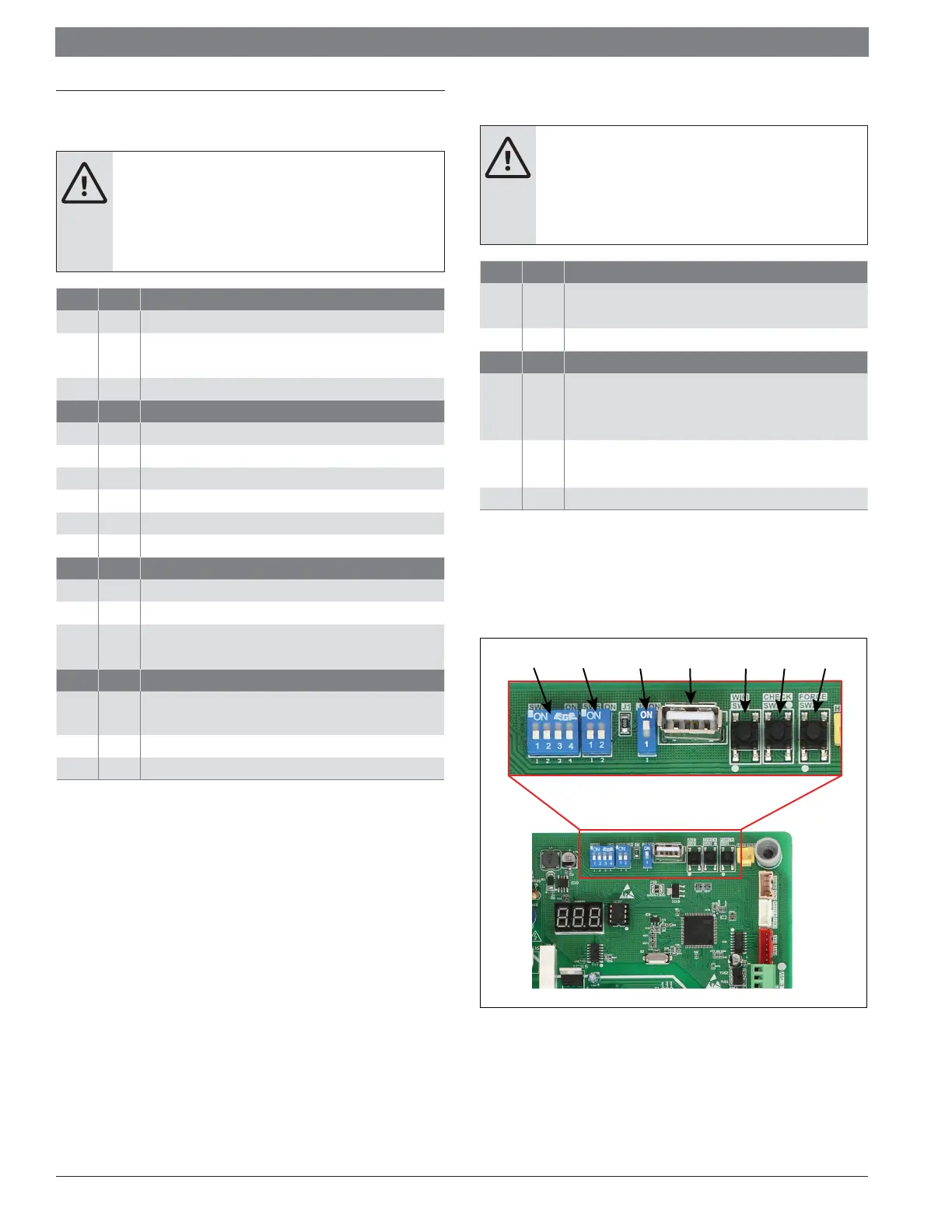
11.3 Dip Switch Settings
11.3.1 Outdoor Unit Dip Switch Settings
Figure 10 3 Ton
SW4 SW5 J2 USB SW1 SW3 SW2
 Loading...