76
|
Bosch IDS 2.0 Service Manual
07.2021 | Bosch Thermotechnology Corp.
Data subject to change
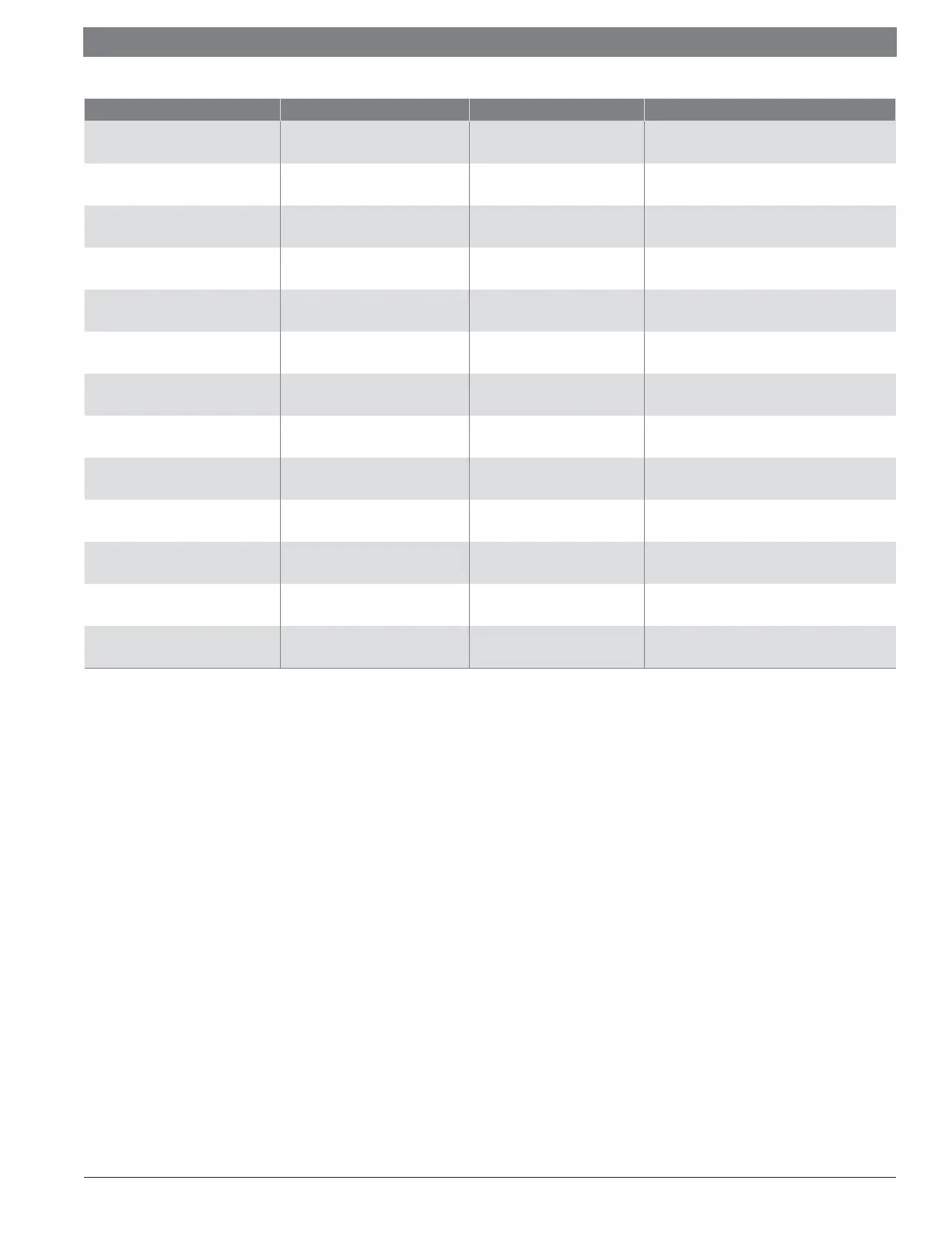
Component Check Measure location Parameter When to check
High voltage power supply
Terminal Block
(L1-L)
172-270V(AC) When there is high voltage power to unit
Low voltage power supply
CN9 Thermostat connection
(Y-C, B-C, W-C)
18-30V(AC) When there is call from thermostat
LED Display DSP1 CODE or numbers When there is high voltage power to unit
DC motor control power
CN3
(+15V-N)
14-18V(DC) When there is call from thermostat
DC voltage
CN3
(P-N)
370-385V(DC) When compressor starts
LED light LED 1/2/3 Light or fl ash When there is call from thermostat
Reversing valve (RV) CN12 Light or fl ash When there is B call from thermostat
CCH - Crank Case Heater CN8 24-36V(AC)
At initial power on/long period in standby mode,
see IOM
PEV - Pressure Equalization Valve CN17 172-270V(AC) At initial power on/start up sequence
EEV – Electronic Expansion Valve
CN13
(All pins-GND)
12V(DC) When there is B call from thermostat
PT - Pressure transducer
CN16
(+5V-GND)
5V (DC) When there is high voltage power to unit
HPS - High pressure switch CN10 1 When power OFF at breaker
Compressor U-V, V-W, W-U <1.5 (3T), <1 (5T) When power OFF at breaker
Table 51 Outdoor Board Component Check
 Loading...