SSB 6720866940 (2017/11) US
Maintenance schedule & procedures | 29
Temperature °F (°C)
Testing tolerance ±10%
Resistance [Ω]
32 (0) 27396
41 (5) 22140
50 (10) 17999
59 (15) 14716
68 (20) 12099
77 (25) 10000
86 (30) 8308
95 (35) 6936
104 (40) 5819
113 (45) 4904
122 (50) 4151
131 (55) 3529
140 (60) 3012
149 (65) 2582
158 (70) 2221
167 (75) 1918
176 (80) 1663
185 (85) 1446
194 (90) 1262
203 (95) 1105
212 (100) 970
221 (105) 855
230 (110) 755
239 (115) 669
248 (120) 594
257 (125) 529
Tab. 12 Resistance values for NTC sensor
9 Electrical supply
9.1 Electrical supply wiring
Connect the boiler to the main electrical supply, as required by local, state
and federal codes.
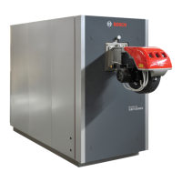
The power supply cables can be inserted into the boiler using one of the
three knock out holes (A) located on each side of the cabinet.
A
Fig. 84 Knock out holes
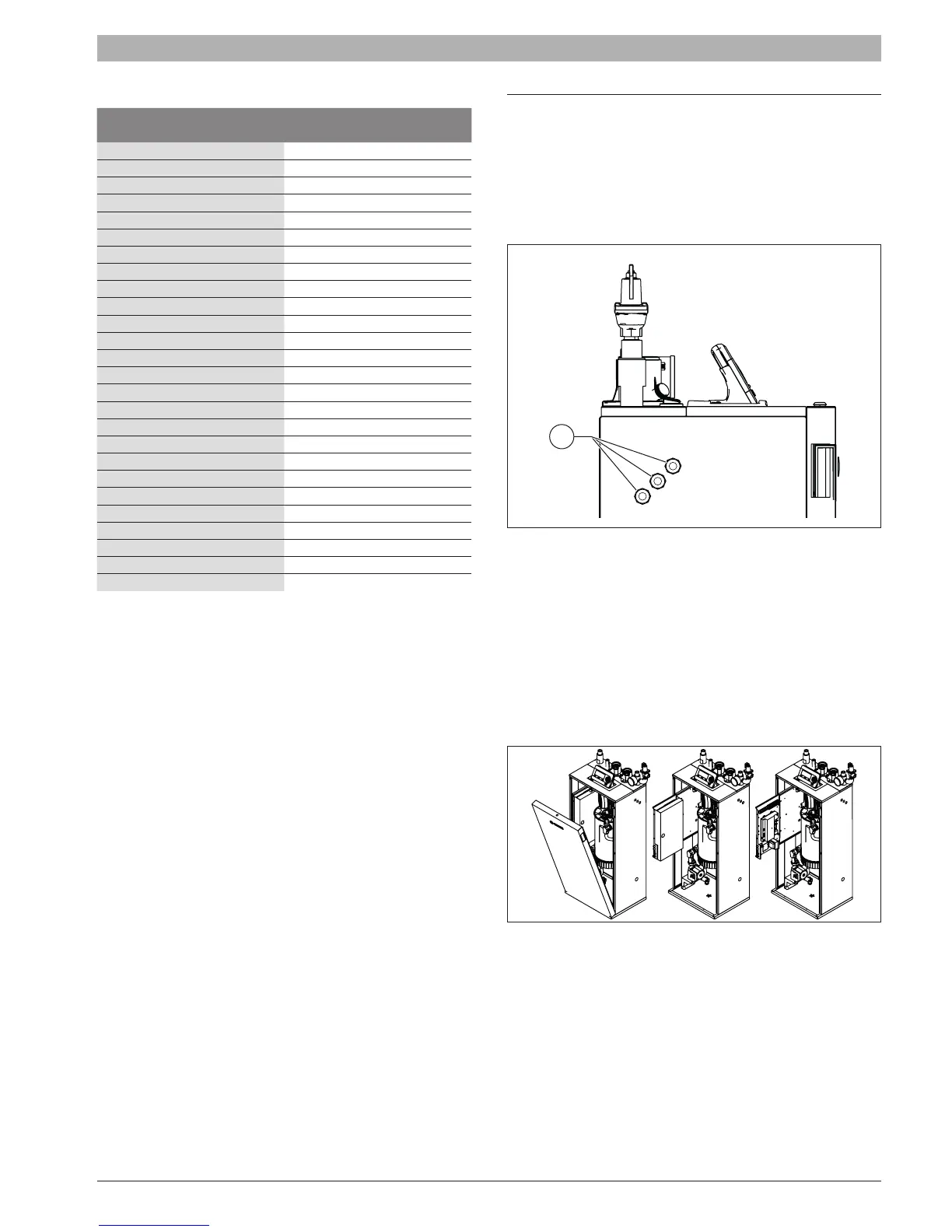
9.2 Access to the electrical terminal strip
To have access to the internal terminal strip of the boiler follow the
procedure below:
[1] Rotate the lock at the top of the front panel and remove the front
panel
[2] Slide out the electrical box and remove the two screws from the
front
[3] Remove the box cover to have access to the terminal strip.
Fig. 85 Access to electrical terminal strip

 Loading...