6720866940 (2017/11) US SSB
30 | Electrical supply
Electrical connection:
123
45
6
7
89
10 11 12 13 14
101102 103104 105106 107108 109
116118117
L
N
L
N
L
N
CASCADE
LINK
MOD
BUS
Gas
Switch
Out
Door
DHW Tank
Sensor
Room
Thermostat
Supply
Sensor
Boiler
Pump
Pump DHW
120 V Main in
N
L
Boiler pump
DHW tank pump
Room thermostat
DHW tank sensor
or aquastat
Outdoor sensor
110111 112
L
N
Alarm
113114 115
L
N
120 V Aux
L
N
Pump CH
N
L
3 Way
120 V Neutral
Ground
120 V Line
Supply sensor
N
L
Relay (*)
Furnished and
Installed by others
(**)
System pump
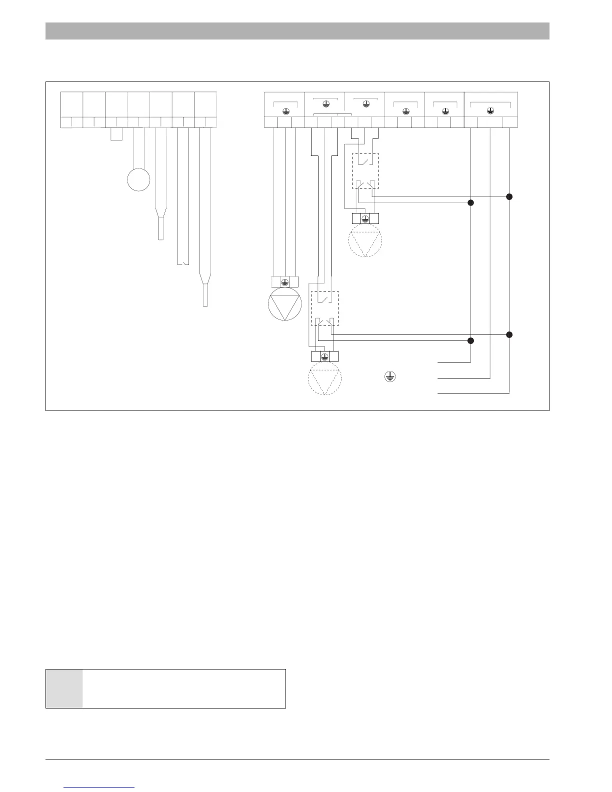
Fig. 86 Electrical connection
9.3 Main electrical supply
Connect the electrical supply and ground to terminals 116-117-118.
9.4 Room thermostat connection
Connect the room thermostat to terminals 11-12.
9.5 DHW tank sensor connection
Connect the DHW tank sensor to terminals 9-10.
9.6 Outdoor temperature sensor
If outside temperature control is to be used, the outside probe needs to
be connected to terminals 7-8. The probe shall be installed on an outer
wall, North or North/East, away from windows, doors and ventilation
grids. Never install the probe in a position exposed to the sun. The
maximum cable length is 300’ (100 meters), if the cable length exceeds
32’ (10 meters) a shielded cable is required and shall be connected to
chassis ground.
WARNING: oute the sensor cable away from High Voltage
cables.
9.7 Supplementary circulating pump relay
The maximum amp load for each pump (in addition to the boiler pump)
is 2Amps when 1 pump is connected. For this reason, if the power
consumption of each pump is higher than 84 watt, a relay (*) must be
used as shown on the diagram above.

 Loading...