103
DISASSEMBLY PROCEDURE
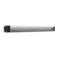
1. Top Cover Removal
1.1 Remove the eight screws that secure the top
cover to the chassis. There are four along the front
edge and four more along the rear edge of the
chassis.
Note: The screws used along the front and rear of
the unit are different types.
1.2 Lift off the top cover.
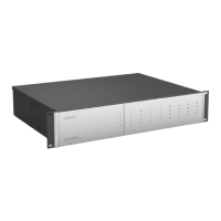
2. 12 - Channel Input PCB Removal
2.1 Perform procedure 1.
2.2 Unplug the ribbon cable at J2203.
2.3 Remove the two screws that secure the PCB
to the rear panel. Remove the seven screws that
secure the PCB to the standoffs inside the chassis.
Lift out the PCB assembly.
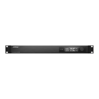
3. 8 - Channel Output PCB Removal
3.1 Perform procedure 2.
3.2 Unplug the ribbon cable at J902.
3.3 Remove the one screw that secures the PCB
to the rear panel.
3.4 Remove the four metal standoffs that secure
the PCB to the chassis. Lift out the PCB assembly.
 Loading...