104
DISASSEMBLY PROCEDURE
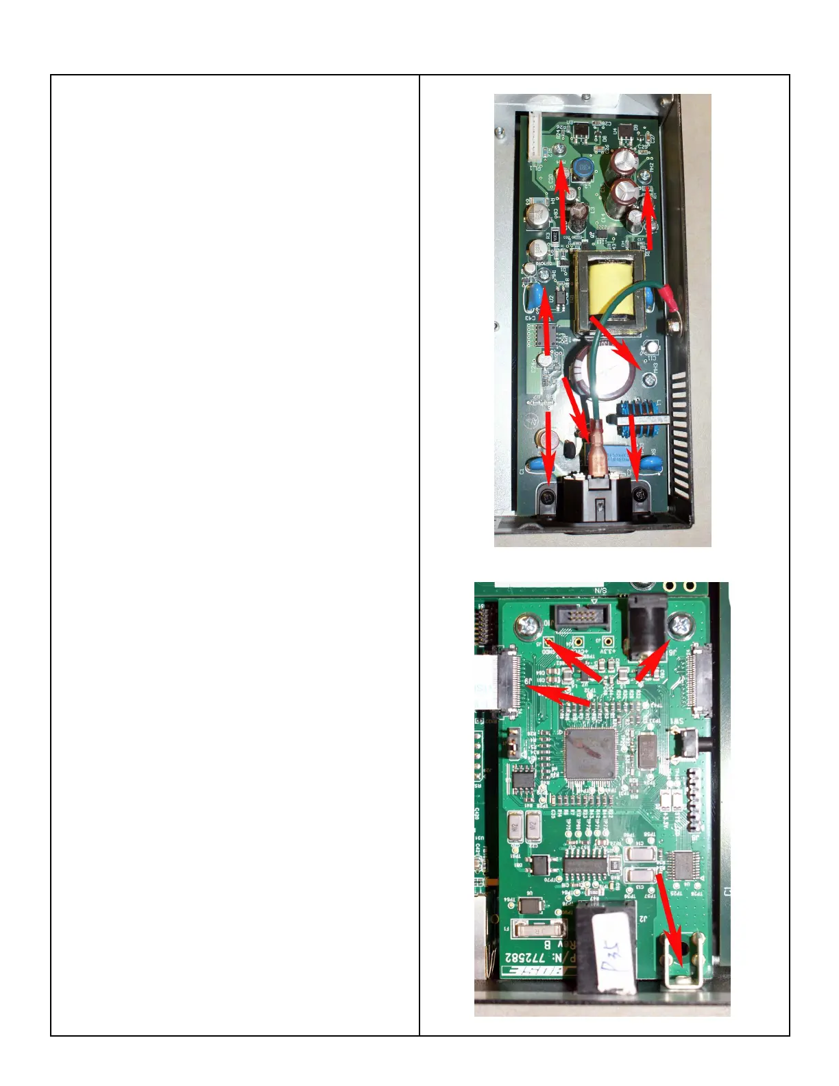
4. Power Supply PCB Removal
CAUTION! There is high voltage located on the
power supply PCB during operation. Be sure to
allow at least one minute for the power supply
to discharge after removing AC mains from the
chassis, and before removing the top cover.
4.1 Perform procedure 1.
4.2 Unplug the wiring harness at PL1.
4.3 Disconnect the ground wire at the IEC
connector by pulling the Faston connector off of
the tab on the back of the AC jack.
4.4 Remove the four silver colored screws that
secure the PCB to the chassis. Remove the two
black screws the secure the AC jack to the chassis.
Lift out the PCB assembly.
CAUTION! During re-assembly, be sure that the
plastic insulation sheet is properly located under
the power supply PCB before re-installing the PCB
assembly. Failure to do so could result in a short-
circuit to the chassis.
5. Public Service Telephone Network (PSTN)
PCB Removal
5.1 Perform procedure 1.
5.2 Disconnect the ribbon cable at J9.
5.3 Remove the one black screw that secures
the PCB to the rear chassis. Remove the two
silver colored screws that secure the PCB to the
standoffs.
5.4 Lift out the PCB assembly.
 Loading...