106
DISASSEMBLY PROCEDURE
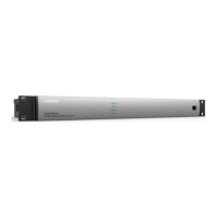
8. Main/DSP PCB Removal
CAUTION! The Main/DSP PCB has a Lithium
battery mounted to the top side of the board. It is
not replaceable, it is soldered in place. DO NOT
dispose of this PCB assembly and/or battery in re.
8.1 Perform procedure 1 to remove the chassis top
cover.
8.2 Perform procedures 5, 6 and 7 to remove the
PSTN, AEC and Dante PCBs from the Main/DSP
PCB.
8.3 Unplug the ribbon cables at J17 (to Output
PCB) and J19 (to OLED Display PCB).
8.4 Unplug the wiring harness from the Power
Supply PCB at J29.
8.5 Unplug the Fan wiring harnesses at the FAN1
and FAN2 connectors.
8.6 Remove the three black screws that secure the
PCB to the rear of the chassis.
8.7 Make a note of the standoff locations, and
remove the six standoffs and four screws that
secure the PCB to the bottom of the chassis.
Note: There is one standoff that is shorter than the
others, and is located near the corner of the Dante
PCB.
8.8 Lift the Main/DSP PCB out of the chassis.
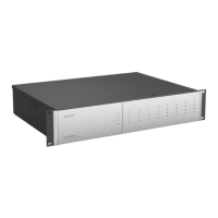
9. Display PCB Removal
9.1 Perform procedure 1.
9.2 Unplug the ribbon cable at J1 (from Main/DSP
PCB).
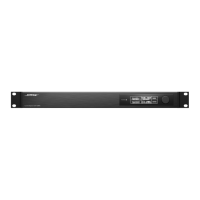
9.3 Gently press on the knob on the front of the
chassis and press outward on the plastic clips that
secure the Display PCB to the plastic carrier.
9.4 Once the Display PCB is free of the clips,
unplug the ribbon cable at J2. This cable connects
to the OLED display.
To remove the OLED display, proceed to step 12.
 Loading...