115
TEST PROCEDURE
22. RS-485 Connection (CC-16) Test
Note: By checking for the CC-16 connection to the UUT, it will respond with the rmware version of the
CC-16 that is connected CC-16 input jack at the RS485 connector. Test passes if the CC-16 is detected.
22.1 Connect a CC-16 Controller to the CC-16 jack on the rear panel. Note: The CC-16 must be powered
using the associated AC power supply in order for it to operate. Refer to the required equipment list at the
beginning of the test procedures for Bose
®
part numbers.
22.2 In ControlSpace Designer, verify that the CC-16 controller is seen as being connected to the DSP
chassis. Pass if the CC-16 is seen in the CSD project window. Fail if the CC-16 cannot be seen.
23. Serial Connection Test
23.1 Connect a DB9 male serial data cable to an
open serial port on the PC.
Note: If your PC does not have a serial
data port, you may have to use a USB to
serial data converter
(such as a Dynex DX-UBDB9). This will allow
you to connect the serial data DB9 cable to the PC’s USB
port through the adapter. Your PC will recognize it as a USB device. You DO NOT need to use a RS232 to
TTL level shifter for this test.
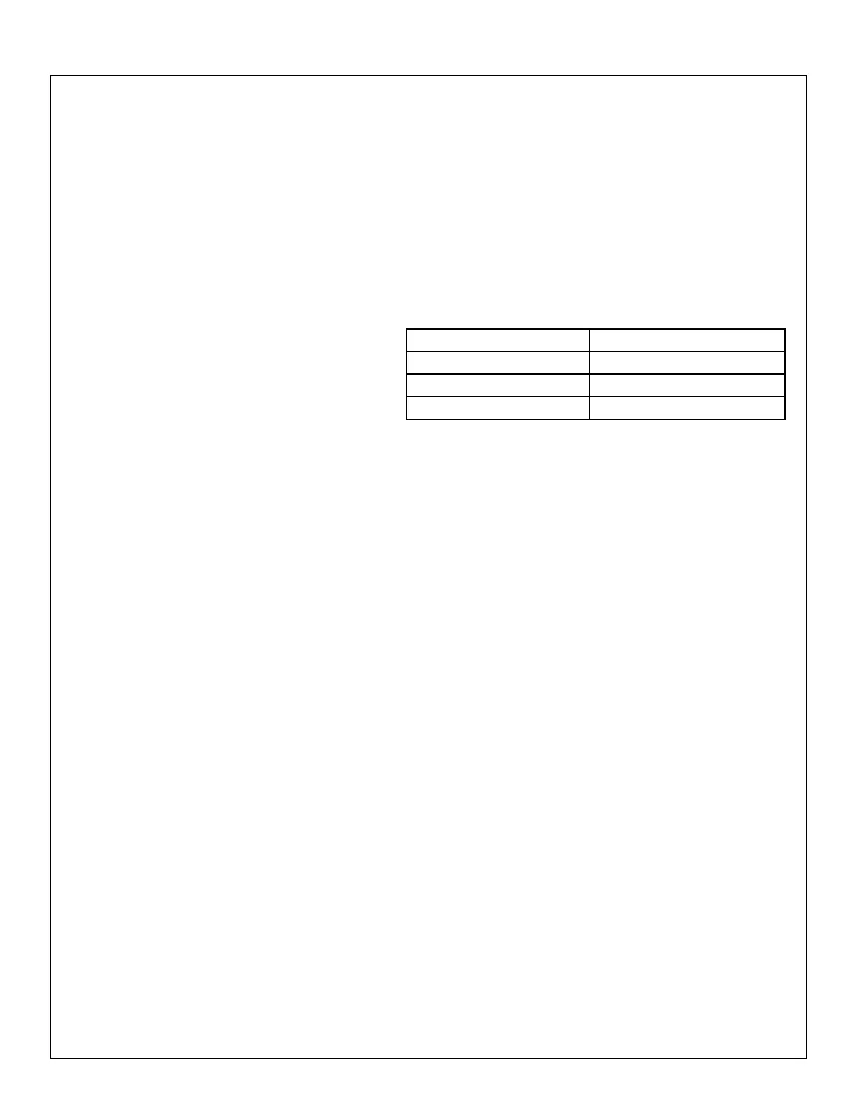
23.2 Using a 3-pin connector, connect the other end of the cable to the Tx, Rx and GND connections on the
EX-1280C. The wiring
should be as shown in the table at right.
23.3 Open a Tera Term window. Select the Serial port or the USB port that the cable is connected to.
Change the Serial Data settings to 115,200, 8, N, 1. Click Connect. Once connected, press the ENTER key
on the keyboard a few times.
23.4 Ensure that the UUT responds with “|>”. If it does, the serial data jack is working. Enter the command
“date”. UUT should respond with the current date and time.
24. Hi-Pot Test
THIS IS A MANDATORY TEST
Note: If this product requires removal of the top cover for repair, it MUST be Hi-Pot tested before being
returned to the customer to ensure that there is no potential shock hazard. This test requires a Hi-Pot tester
with a ground bond attachment to perform this test.
Connections:
The Hi-Pot tester connects to the Unit Under Test (UUT) by means of a wiring harness. The AC line cord
of the UUT plugs into the Hi-Pot tester AC adapter box. The return line connects to an accessible chassis
ground point using an alligator clip. There are no special cables required for this test.
Hi-Pot Tester Settings:
All units - 2500 VAC, rise time = 1 sec., dwell = 1 to 4 seconds, current limit = 1.2 mA
24.1 Connect the AC mains cord to the back of the Unit Under Test (UUT). Plug the other end of the AC
cord into the Hi-Pot tester.
EX-1280C Serial Port DB9 Connector Pinout
Tx Pin 2 (Receive Data)
Rx Pin 3 (Transmit Data)
GND Pin 5 (Ground)
 Loading...