34
DISASSEMBLY PROCEDURE
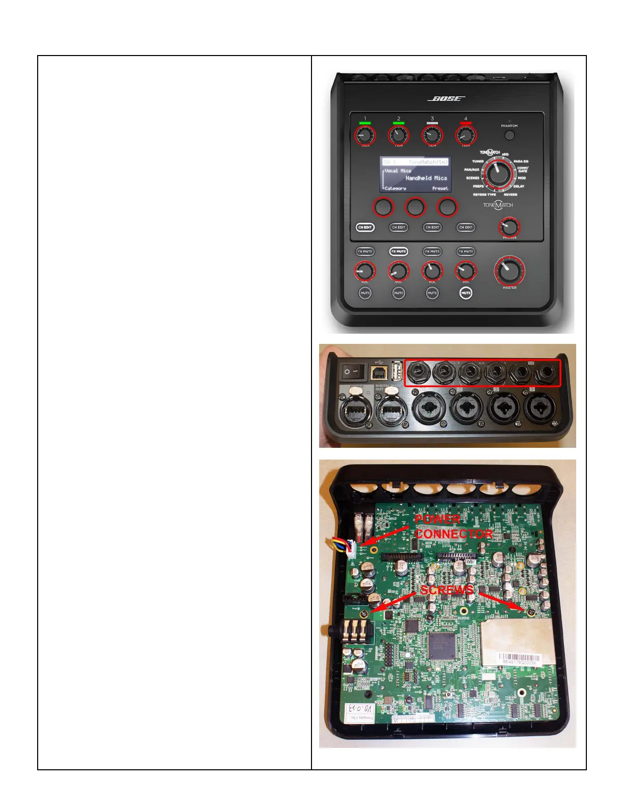
3. Main PCB Removal
3.1 On the front panel, carefully remove the
fourteen knobs by pulling them straight off.
3.2 Perform procedure 2 to remove the I/O PCB
assembly.
3.2 On the I/O panel, remove the six plastic nuts
that secure the 1/4” TRS jacks.
3.3 On the Main PCB, disconnect the wiring
harness for the power switch at connector P2.
3.4 Remove the two screws that secure the Main
PCB to the top housing. Lift out the Main PCB
assembly.
Re-assembly Note: Be sure that the rubber
buttons and phantom power button are properly
aligned with the top housing when re-installing
the Main PCB.
 Loading...