35
DISASSEMBLY PROCEDURE
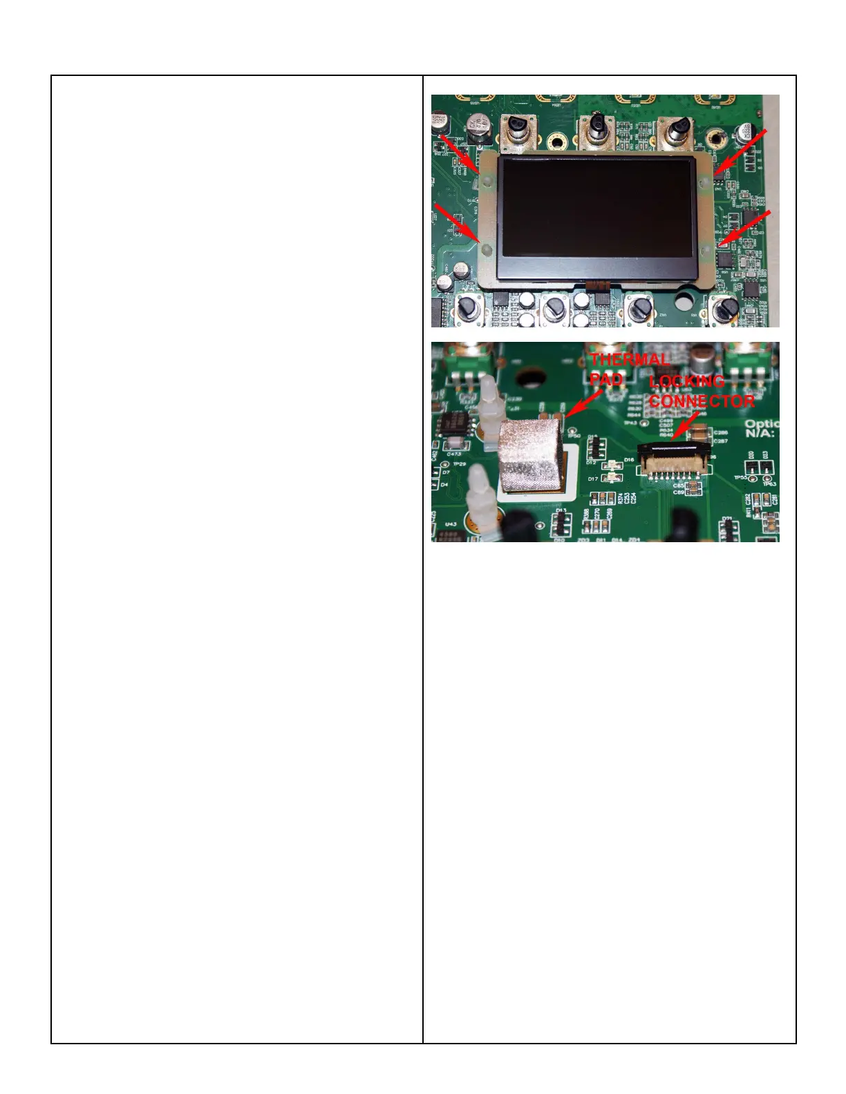
4. LCD Display Assembly Removal
4.1 Perform procedure 3 to remove the Main
PCB assembly.
4.2 Using a pair of needle-nose pliers,
compress the legs of the nylon standoffs that
secure the LCD Display assembly the Main
PCB assembly.
4.3 Carefully lift up the LCD Display assembly.
Lift the black locking tab for the connector and
and unplug the ribbon cable from the Main
PCB at J12.
4.4 Lift off the LCD Display assembly.
Re-assembly note: Be sure that the cube-
shaped thermal pad is in place before re-
installing the LCD display onto the nylon posts.
Refer to the photo at right.
 Loading...