GENERAL
Identification
For model identification, see the nameplate mounted on
the side of the exhaust box.
This manual is written to cover RA and RC versions of
models 0025, 0040, 0063, 0100, 0101 and 0250 with a
"C" or "E" appearing as the seventh character in the
model type number stamped into the nameplate. For
example, it would appear as follows:
RAXXXX-C
XXX-XXXX
When ordering parts, it is helpful to include the identifi-
cation code stamped into the side of the cylinder as well
as the serial number from the nameplate.
Operating Principles
All reference (Ref. XXX) numbers listed in the text and
on illustrations throughout this manual are related to the
drawings and parts list shown later in this publication.
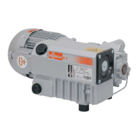
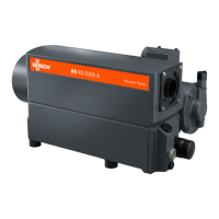
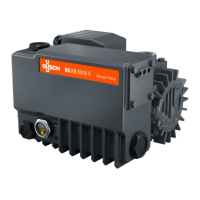
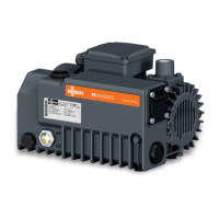
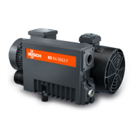
All R 5 Series, Single Stage, Rotary Vacuum Pumps are
direct-driven, air-cooled, oil-sealed, rotary vane pumps
that operate as positive displacement pumps. They
consist of a rotor positioned eccentrically in a cylindrical
stator (see Fig. 1). The rotor has three radially sliding
vanes which divide the pump chamber into three seg-
ments. When the rotor spins, centrifugal force pushes
the vanes, which glide in the slots, towards the wall of
the cylinder. The rotor has three vanes which divide the
pump chamber into three segments. The gas to be
pumped enters at the inlet port, passes through the inlet
screen and the open anti-suck-back valve into the
pump chamber. As the rotor rotates, the inlet aperture
is closed, the gas is compressed and forced out through
one-way valves between the pump cylinder and the
exhaust box. This operation is repeated three times
each revolution.
1.0 INSTALLATION
1.1 Unpacking
Inspect the box and pump carefully for any signs of
damage incurred in transit. Since all pumps are ordi-
narily shipped FOB our factory, such damage is the nor-
2
mal responsibility of the carrier and should be reported
to them.
Remove the nuts from the bottom of the box/crate and
pull the pump out of the container, then unscrew the
studs from the bottom of the rubber feet.
The inlet port of the pump is covered with a plastic cap
prior to shipment to prevent dirt and other foreign mate-
rial from entering the pump. Do not remove this cover
until the pump is actually ready for connection to your
system.
1.2 Location
The pump must be installed in a horizontal position on
a level surface so that the pump is evenly supported on
its rubber feet. Allow sufficient air space between the
pump and any walls or other obstructions; adequate
ventilation must be provided for the fans on the pump
and motor (i.e., do not locate the pump in a stagnant air
location).
Whenever the pump is transported, be sure to drain the
oil prior to shipping to avoid vane breakage when
restarting the pump.
Do not tip the pump over if it is filled with oil.
Locate the pump for easy access to the oil sight glass
(Ref. 83) in order to inspect and control the oil level
properly. Allow clearance at the exhaust flange area to
provide service access to the exhaust filters.
1.3 Power Requirements
The schematic diagram for the electrical connection is
located in the junction box or on the nameplate of the
pump motor.
The motor must be connected according to the electri-
cal codes governing the installation. The power supply
must be routed through a fused switch to protect the
motor against electrical or mechanical overloads. The
motor starter has to be set consistent with the motor
current listed on the motor nameplate.
If the pump is supplied with a manual motor starter, it is
preset at the factory in accordance with the customer’s
specification. For other voltage requirements, contact
the factory for motor and/or starter information.
Note: See the motor manufacturer’s manual for start-
up maintenance of the motor.
Correct direction of rotation is marked by an arrow on
the motor fan housing and is counterclockwise when
looking at the motor from the motor's fan side.
All R 5 series pumps are designed to handle air.
Vapor in the air stream can be tolerated when the
pump is operated within certain operating parameters
as defined by Busch, Inc. Engineering (see Section
2.2 - Gas Ballast). When you desire to use the pump
on an air stream that contains vapors, contact Busch,
Inc. Engineering for operating recommendations; oth-
erwise, the warranty could be void.
 Loading...