Page 19 - Manual FA01383-EN - 04/2021 - © CAME S.p.A. - The contents of this manual may be changed at any time and without notice. - Translation of the original instructions
Maximum capacity of contacts
Device Output Power supply (V) Power (W)
Accessories 10 - 11 24 AC 40
Additional light 10 - E1 24 AC 25
Flashing beacon 10 - E1 24 AC 25
Operator status warning light 10 - 5 24 AC 3
RGB LED strip +RG 24 DC 12
Electric lock Eb- - Eb+ 24 DC 5
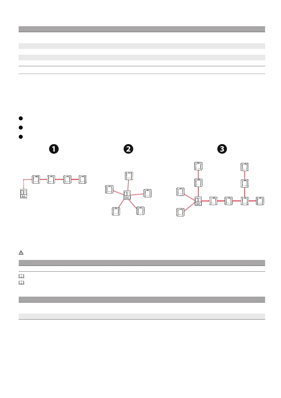
Devices with BUS CXN system
The CXN CAME system is a two-wire non-polarised communication BUS which allows you to connect up all compatible CAME devices.
Connection to the BUS can be in a chain, star or mixed formation.
Once the system has been wired, and after having set the address on each device, the function of each accessory can be configured on the control panel. This
method allows you to configure the set-up immediately without having to do so later and intervene directly on the accessories and system wiring.
The CXN BUS can support control devices, photocells, safety devices, beacons and gateways at the same time.
Cabling
1
Chain connection
2
Star connection
3
Mixed connection
Cable type
We recommend using a FROR 2 x 0.5 mm cable, maximum 50 m in length from the control board.
Single branch length (m) max. 50 m
BUS cable 2 x 0.5 mm²
The total length of all branches can be a maximum of 150 m.
The cable cannot be shielded.
Maximum number of devices that can be connected, by type
Type of device Maximum number of devices
Keypad selectors and transponders 7
Photocell pairs 8
Flashing beacons 2

 Loading...