Page 6 - Manual FA01383-EN - 04/2021 - © CAME S.p.A. - The contents of this manual may be changed at any time and without notice. - Translation of the original instructions
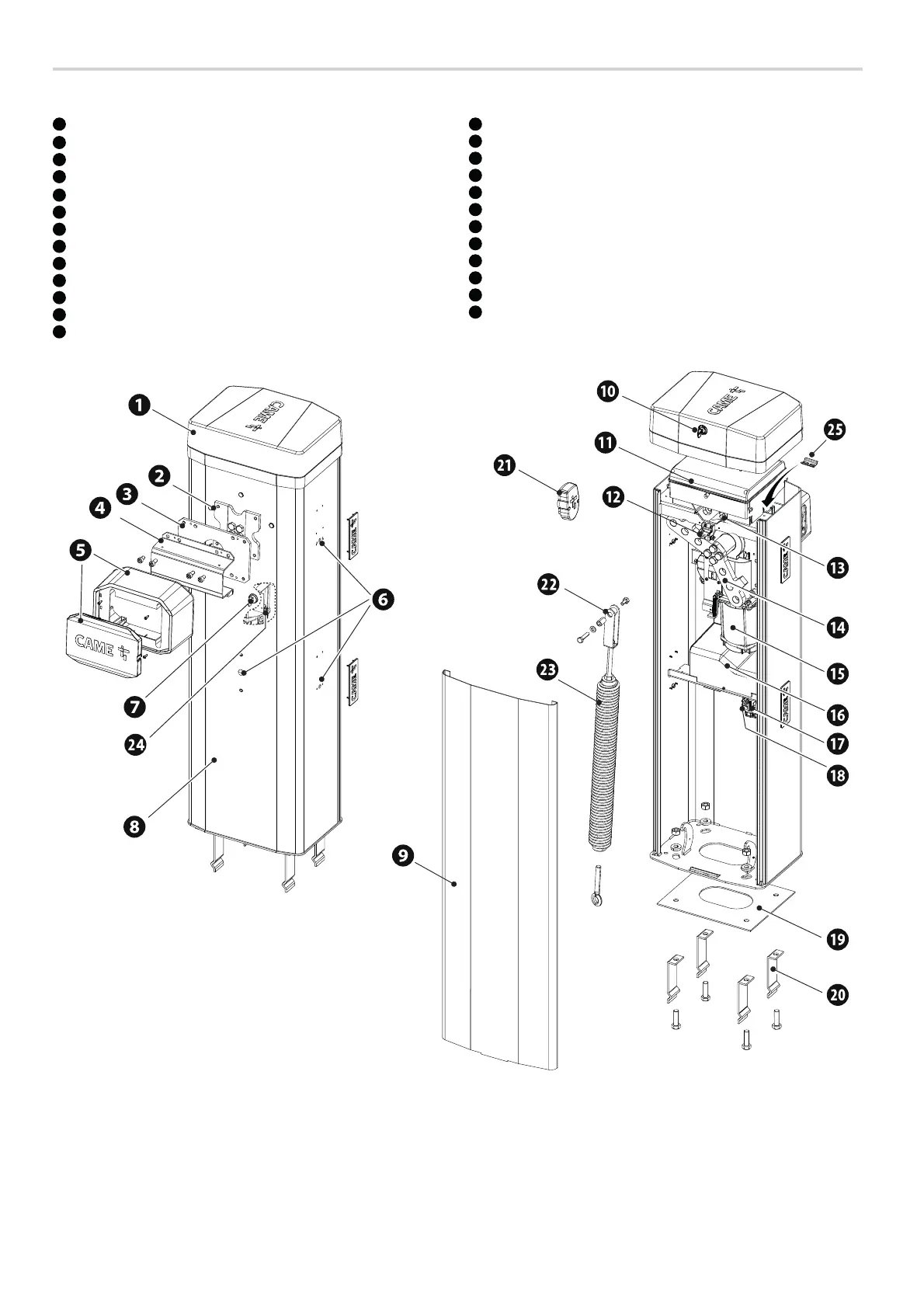
Description of parts
Barrier
1
Cover
2
Boom anchoring plate
3
Intermediate plate
4
Fastening flange
5
Anti-shearing cover
6
DIR/DXR photocell holes
7
Lock for release
8
Cabinet
9
Inspection hatch
10
Inspection-hatch lock
11
Control panel
12
Safety microswitch with cover open
13
Mechanical stop for the boom adjustment
14
Lever arm
15
Gear motor with encoder
16
Auxiliary
17
Line fuse
18
Power supply terminal board
19
Anchoring plate
20
Anchoring bracket
21
Boom profile end cap
22
Spring anchoring pin
23
001G06080 - Balance spring Ø 55 mm.
24
Released gearmotor safety microswitch
25
DIN rail

 Loading...