15
c.pCO
A
110
45
B
44
pGDE
pGD1
156
125
67
18
30
82
202
53
43
177
70 63
110
132
45
c.pCO mini
c.pCO mini, panel mounting
148
82
70.5
81.0
59.5
38.1
134
Ø 4
34.5
dima di foratura
drilling template
127x69 mm
Ø 4
ENG
c.pCO sistema +0300057EN rel. 1.2 - 29.05.2017
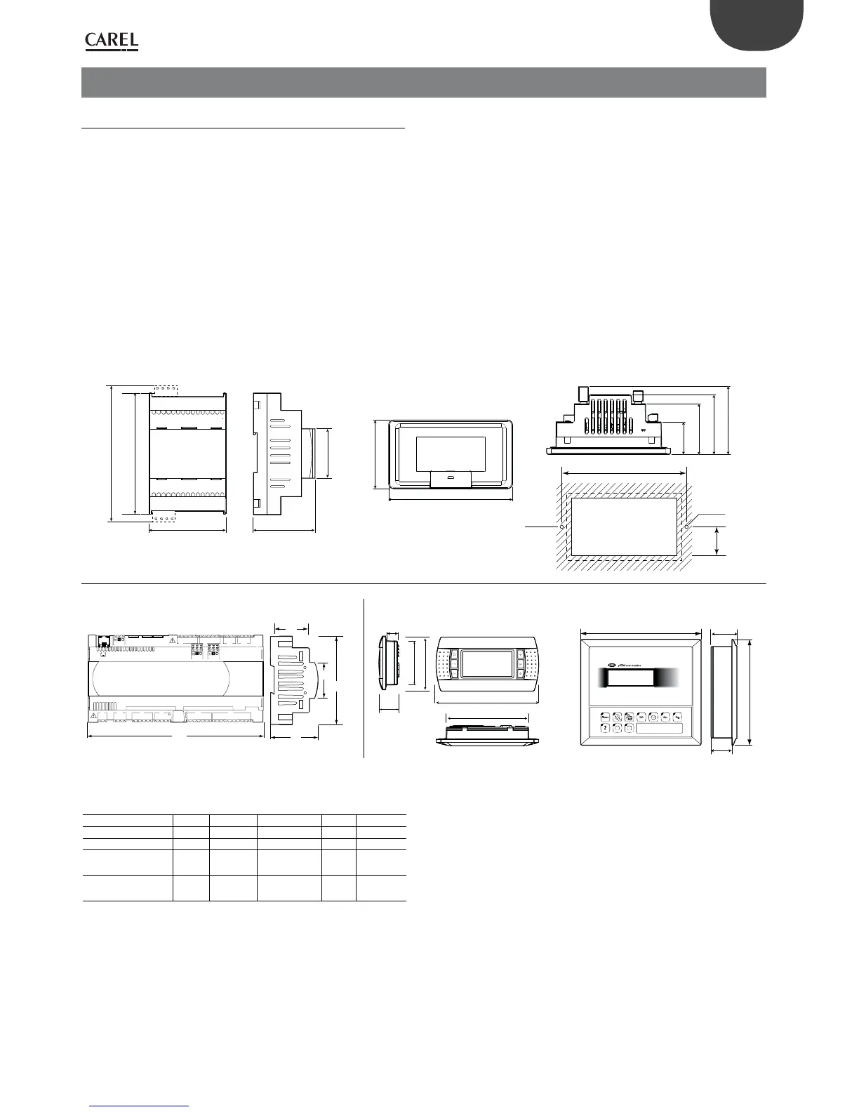
4. INSTALLATION
4.1 Mounting and dimensions
All models in the c.pCO family can be mounted on a DIN rail, except for
the c.pCOmini panel version.
DIN rail assembly: c.pCOmini, c.pCO Small...Extralarge
The following gure shows the dimensions of the c.pCO controllers,
according to the model.
Mounting:
• place the controller on the DIN rail and press it down gently. The tabs
at the back will snap into place and lock the controller.
Removing:
• lift the tabs using a screwdriver applied to their release slots. The tabs
are kept in place by springs.
Fig. 4.a
Dimensions (mm)
Small Medium Buit-in driver Large Extralarge
A 227,5 315 315 315 315
B 60 60 60 60 60
B -
with USB port /
built-in terminal
70 70 70 70 70
B -
with ULTRACAP
module
-- 75 --
Tab. 4.a

 Loading...


