45
ENG
c.pCO sistema +0300057EN rel. 1.2 - 29.05.2017
6.7 c.pCOe expansion board: installation
and configuration
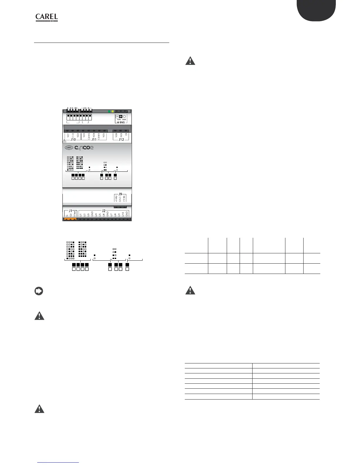
c.pCOe is an I/O expansion module compatible with the c.pCO and pCO
sistema platforms. The module features:
• 10 universal inputs/outputs that can be congured in the
application program to connect active and passive probes, digital
inputs, analogue and PWM outputs.
• 6 relay digital outputs, divided into 3 groups (see paragraph 5.7)
• Power supply terminals for ratiometric probes and active probes
• Built-in BMS serial interface
• Dipswitches for conguring the communication protocol and serial
address
1
2
3
4
5
6
7
8
9
10
11
12
13
14
15
with oset
no oset
19.2 K
9.6 K
38.4 K
57.6 K
CAREL
Modbus
ON
OFF
Address Ext. ProtBaud
Address Ext Baud Prot
Fig. 6.o
1
2
3
4
5
6
7
8
9
10
11
12
13
14
15
with oset
no oset
19.2 K
9.6 K
38.4 K
57.6 K
CAREL
Modbus
ON
OFF
Address Ext. ProtBaud
Fig. 6.p
Note: the green LED indicates communication status on the BMS
port. If there is communication on the BMS port (online) the green LED
ashes, if there is no communication (oine) the LED stays on steady.
Important: Power supply to the product must only be connected
between G and G0. The Vbat terminal is only used for connection to the
Ultracap module as emergency power supply in the event of a power
failure.
The dipswitches can be used to set the expansion board serial address
(from 1 to 15), protocol (Modbus or Carel) and baud rate. By serial
connection it is possible to modify the electrical conguration of the line
and assign a serial address from 16 to 247 (207 if using the Carel protocol).
Baud rate and communication protocol settings
Board default conguration is baud rate 19.2 Kbps and Modbus protocol.
The “Baud” and “Prot” dipswitches (see Fig. 6.u) can be used to set the baud
rate and the communication protocol used by the expansion board. The
unit must be switched o before making the settings on the dipswitches.
Important: if the baud rate and protocol settings are changed on
the dipswitches while the unit is on, this must be restarted to activate the
new settings.
Address and serial communication mode settings
To assign to the board a serial address from 1 to 15, simply set the
dipswitches as shown in Figure 6.u. The “Ext” dipswitch must be set to
“OFF” (no oset). The unit must be switched o before making the
settings on the dipswitches.
Important: if the settings are changed on the dipswitches while
the unit is on, this must be restarted to activate the new settings.
To assign to the the board a serial address from 16 to 247 and to congure
the serial communication settings, an oset needs to be sent to the
expansion board via serial communication, which is then added to the
“Address” dipswitch conguration, and the variable corresponding to the
serial transmission parameters needs to be set, as follows:
Example (address setting N=87, serial communication 8, Even, 1):
1. Set the dipswitches of the “Address” group and the dipswitch “Ext.”
a OFF.
2. Restart the unit. The c.pCOE will go into “Set Mode”. Warning:
activating this mode resets both the address oset and the serial
communication settings. In this mode, the board serial address will
be 207 and the serial conguration will be 8 bits, no parity and 2 stop
bits (8 bits, None, 2). The yellow LED ashes.
3. To set the communication parameters, the “Serial Transmission
Conguration” variable needs to be set via serial communication
(see Table 6.a and 6.b). In this example, the variable is set to 5
(conguration 8, Even, 1).
4. To set the serial address, the “Address Extension” oset variable needs
to be set via serial communication (the oset must be greater than
14, see Table 6.a). In this example, it can be set to 86.
5. Move the “Ext” dipswitch to ON. Set the “Address” dipswitches to a
value greater than 0. In this example, the value is set to 1.
6. Restart the unit. After restarting, the expansion card will be
congured with the serial address calculated as the sum of the value
set for the “Address Extension” variable and the value set on the
“Address” dipswitches (in this example 86 + 1 = 87). After restarting,
the expansion card will have the serial communication conguration
8, Even, 1.
Variable Carel
Address
(Integer)
Min
Value
Carel
Max
Value
Carel
Modbus Address
(Holding Regi-
ster)
Min
Value
Modbus
Max
Value
Modbus
Address
Extension
14 15 192 14 15 232
Serial Con-
guration
17 0 5 17 0 5
Tab. 6.a
Important:
• If using the Carel protocol, the maximum settable oset is 192.
• The following congurations are not allowed:
- The “Ext” dipswitch cannot be ON with an oset equal to 0 (“Address
Extension” variable = 0). In this case, the card will signal a conguration
error, with the yellow LED on steady. The green LED remains on,
indicating that the card is oine.
- The “Ext” dipswitch cannot be ON with an oset other than 0 and
the “Address” dipswitches set to 0 (all OFF). In this case, the card will
signal a conguration error, with the yellow LED ashing. The green
LED remains on, indicating that the card is oine.
Serial Conguration
Value Conguration
0 8, none, 2
1 8, none, 1
2 8, odd, 2
3 8, odd, 1
4 8, even, 2
5 8, even, 1
Tab. 6.b

 Loading...


