Presente solo nelle configurazioni che utilizzano l'ingresso digitale
come contatto d'allarme (vedi C26, vedere par. “Descrizione dei para-
metri selezionabili”).
Stato delle Uscite
Dipende dalla configurazione impostata (parametro C26, cap.8.2).
Possibili Interventi
Verificare i collegamenti controllo-dispositivo e il corretto funzionamen-
to di questo. Se il contatto dei morsetti D.in/Ref. è chiuso, l'allarme è
disattivato. Controllare il parametro di configurazione C26.
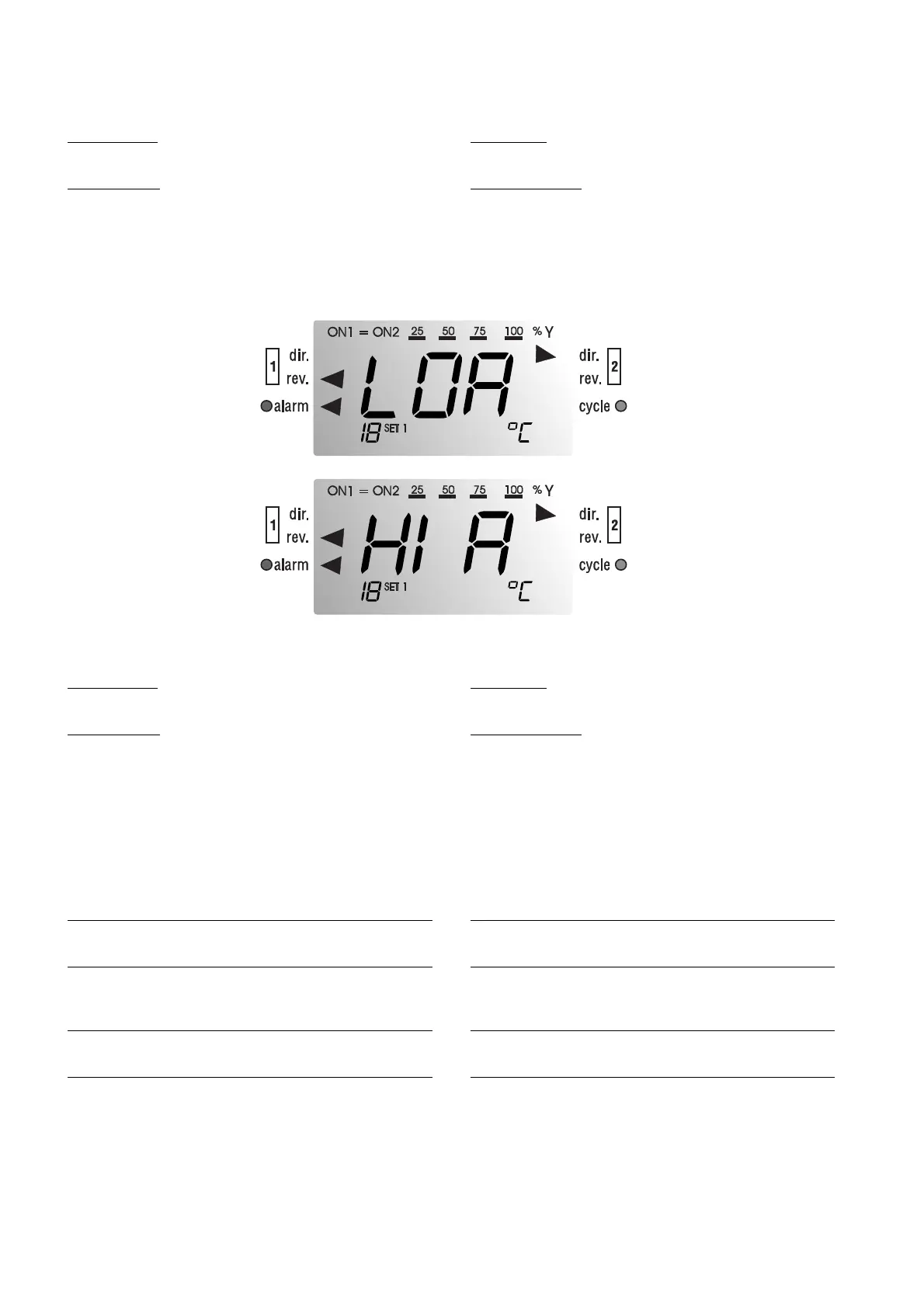
LOA - Allarme di Superamento del Limite Inferiore
HIA - Allarme di Superamento del Limite Superiore
Attivato qualora siano superati i limiti inferiore (LOA) o superiore (HIA)
impostati.
Stato delle Uscite
Non subisce variazioni.
Possibili Interventi
Verificare se la grandezza regolata ha superato i valori massimi di sco-
stamento rispetto ai Set-Point impostati nei parametri P14 e P15.
Provvedere eventualmente ad aumentare i limiti impostati se fossero
troppo stretti.
12. Caratteristiche tecniche
Alimentazione:
24 Vac ±15%, e 220/240 Vac (Limiti 180-264 Vac) 50/60 Hz
Dimensioni contenitore:
per montaggio a pannello, frontale 72x72 mm, profondità 102,5 mm,
dima 68x68 mm (v. pag. 46)
Grado di protezione frontale:
IP55 con strumento montato a pannello e guarnizione inserita
Uscite:
CR721 un relè SPDT con pot. max. comm. 2000 VA res., 250Vac, 8A
CR722 due relè SPDT con pot. max. comm. 2000 VA res., 250Vac, 8A
uscita analogica (opzionale) multistandard:
in corrente 0/20 mA
in corrente 4/20 mA
in tensione 0/1 Vdc
in tensione 0/10 Vdc
la scelta è eseguita tramite 8 dip-switch
It can occur exclusively in the models where the digital input works as
an alarm contact.
Outputs' status
Depends on the selected configuration (ch.4).
P
ossible Interventions
Check the control-device connections. If the contact at terminals
D.in/Ref. (digital input/reference) is closed, the alarm disappears. Check
the configuration parameter C26.
LOA - Lower Limit Alarm (overshot lower limit)
HIA - Higher Limit Alarm (overshot higher limit)
These messages appear when the lower (LOA) or higher (HIA) selec-
ted limits are overshot.
Outputs' status
No variation
P
ossible Interventions
Check that the controlled parameter has not overshot the maximum
variation value with respect to the Set-Points selected through the P14
and P15 parameters. In case the limits do not suit the actual needs,
increase their values.
12.Technical specifications
Power Supply:
24Vac ±15%, and 220/240Vac (Limits 180-264Vac), 50/60Hz
Case:
panel mounting, front panel 72x72mm, depth 102.5mm, drilling templa-
te 68x68mm
Front Panel Protection Index:
IP55 with the instrument panel mounted and gasket inserted
Outputs:
CR721 SPDT relay with max. switchable power 2000VA res.
, 250Vac, 8A
CR722 two SPDT relays with max. switchable power 2000VA res.,
250Vac, 8A
multi-standard analog output (optional):
current 0/20 mA
current 4/20 mA
voltage 0/1 Vdc
voltage 0/10 Vdc
8 dip-switches allow user to make the required selection
44
 Loading...


