pCO Sistema
Code: +030220336 - rel. 1.5 - 22/12/10
14
2.3 pCO
1
controller
Rx-/Tx-
Rx+/Tx+
GND
C1
NO1
NO2
NO3
C1
C4
NO4
NO5
NO6
C4
C7
NO7
C7
NO8
C8
NC8
NO13
C13
NC13
C9
NO9
NO10
NO11
C9
G
G0
B1
B2
B3
B4
+VDC
B5
GND
B6
GND
VG
VG0
Y1
Y2
Y3
Y4
ID1
ID2
ID3
ID4
ID5
ID6
ID7
ID8
IDC1
B7
GND
B8
GND
ID9
ID10
ID11
ID12
IDC9
ID13H
ID13
IDC13
ID14
ID14H
Fuse
Analog Selection Serial Card
Clock card
Programming Key
J1
J2
J3
J5
J6
J7
J8
J10
J11
J12
J13
J14
J15
J16
J17
J18
+5V Rif
GND
+V Term
J9
J4
10
1
11
12
14
3
7
8
4
6
5
8
9
2
16
15
17
13
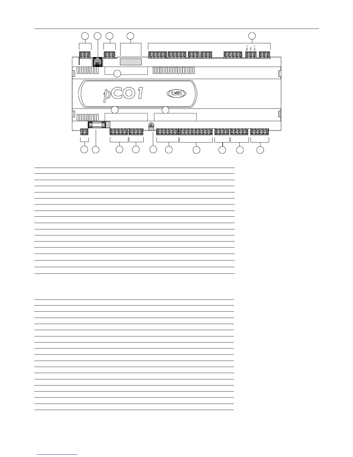
Fig.. 2.d
Fig.. 2.dFig.. 2.d
Fig.. 2.d
Key:
Key:Key:
Key:
1. power supply connector [G (+), G0 (-)]
2. 250 Vac, 2 A slow-blow fuse (T2 A)
3. universal analogue inputs: NTC, 0/1V, 0/5 V, 0/20 mA, 4/20 mA
4. passive analogue inputs: NTC and ON/OFF
5. passive analogue inputs: NTC
6. yellow power LED and 3 status LEDs (see paragraph 6.3)
7. 0 to 10 V analogue outputs and PWM outputs
8. 24 Vac/Vdc digital inputs
9. 230 Vac or 24 Vac/Vdc digital inputs
10. connector with Vref for power supply to 5V ratiometric probe and V term for power supply to Aria terminal
11. connector for all standard pCO* series terminals and for downloading the application program
12. pLAN network connector
13. programming key connector
14. relay digital outputs
15. port for selecting the type of analogue inputs
16. cover for inserting the optional supervisor and telemaintenance board
17. cover for inserting the clock board
2.3.1
2.3.12.3.1
2.3.1 Meaning of
Meaning of Meaning of
Meaning of the pCO
the pCOthe pCO
the pCO
1
11
1
inputs/outputs
inputs/outputsinputs/outputs
inputs/outputs
Connector
Connector Connector
Connector
Signal
Signal Signal
Signal
Description
DescriptionDescription
Description
J1-1 G +24 Vdc or 24 Vac power supply
J1-2 G0 power supply reference
J2-1 B1 universal analogue input 1 (NTC, 0/1V, 0/5 V, 0/20 mA, 4/20 mA)
J2-2 B2 universal analogue input 2 (NTC, 0/1V, 0/5 V, 0/20 mA, 4/20 mA)
J2-3 B3 universal analogue input 3 (NTC, 0/1V, 0/5 V, 0/20 mA, 4/20 mA)
J2-4 B4 universal analogue input 4 (NTC, 0/1V, 0/5 V, 0/20 mA, 4/20 mA)
J2-5 +VDC 24 Vdc power supply for active probes (maximum current 100 mA)
J3-1 B5 passive analogue input 5 (NTC, ON/OFF)
J3-2 GND common for analogue input 5
J3-3 B6 passive analogue input 6 (NTC, ON/OFF)
J3-4 GND common for analogue input 6
J4-1 VG power to optically-isolated analogue output, 24 Vac/Vdc
J4-2 VG0 power to optically-isolated analogue output, 0 Vac/Vdc
J4-3 Y1 analogue output no. 1, 0/10 V
J4-4 Y2 analogue output no. 2, 0/10 V
J4-5 Y3 analogue output no. 3, PWM (for phase cutting speed controllers)
J4-6 Y4 analogue output no. 4, PWM (for phase cutting speed controllers)
J5-1 ID1 digital input no. 1, 24 Vac/Vdc
 Loading...


