pCO Sistema
Code: +030220336 - rel. 1.5 - 22/12/10
43
5.2 Installing the pGD0 and pGD1 terminals
The connection between the terminal and the pCO is made using a 6-wire telephone cable, supplied by CAREL (code S90CONN).
To make the connection, simply plug the telephone connector into the RJ12 jack on the rear of the terminal, and in connector:
• J19 on the pCO
C
;
• J5 on the pCO
XS
;
• J10 on the pCO
1
, pCO
3
.
The address of the terminal can be set in the range between 0 and 32; addresses from 1 to 32 are used by the pLAN protocol, while address 0 identifies the Local terminal
Local terminal Local terminal
Local terminal
protocol
protocolprotocol
protocol, used for point-to-point connections without graphics and to configure the pCO. The default address is 32. The address can only be set after having powered up the
terminal via the RJ12 connector. To access configuration mode, press the UP, DOWN and ENTER ( , , ) buttons together for at least 5 seconds; the terminal will display a
screen similar to the one shown below, with the cursor flashing in the top left corner:
Display address
.Fig. 5.d
Fig. 5.dFig. 5.d
Fig. 5.d
To change the address of the terminal (“Display address setting”), proceed as follows.
Press the ENTER button once: the cursor will move to the “Display address setting” field.
Select the desired value using the UP and DOWN buttons, and confirm by pressing ENTER again.
If the value selected is different from the value previously saved, the following screen will be displayed and the new value will be saved to the permanent memory.
Display address
changed
Fig. 5.
Fig. 5.Fig. 5.
Fig. 5.e
ee
e
If the address field is set to 0, the terminal communicates with the pCO board using the Local terminal protocol and the “I/O Board address” field is no longer shown,
as it has no meaning.
To change the list of terminals (private and shared) associated with a pCO board, proceed as follows:
- enter configuration mode (see above) by pressing the UP, DOWN and ENTER buttons together for at least 5 seconds.
- press the ENTER button twice: the cursor will move to the “I/O Board address” field.
- select the address of the desired pCO board and confirm by pressing ENTER.
The pCO will then enter the configuration procedure, showing a screen similar to the one below.
Terminal config
Press ENTER
to continue
Fig. 5.
Fig. 5.Fig. 5.
Fig. 5.f
ff
f
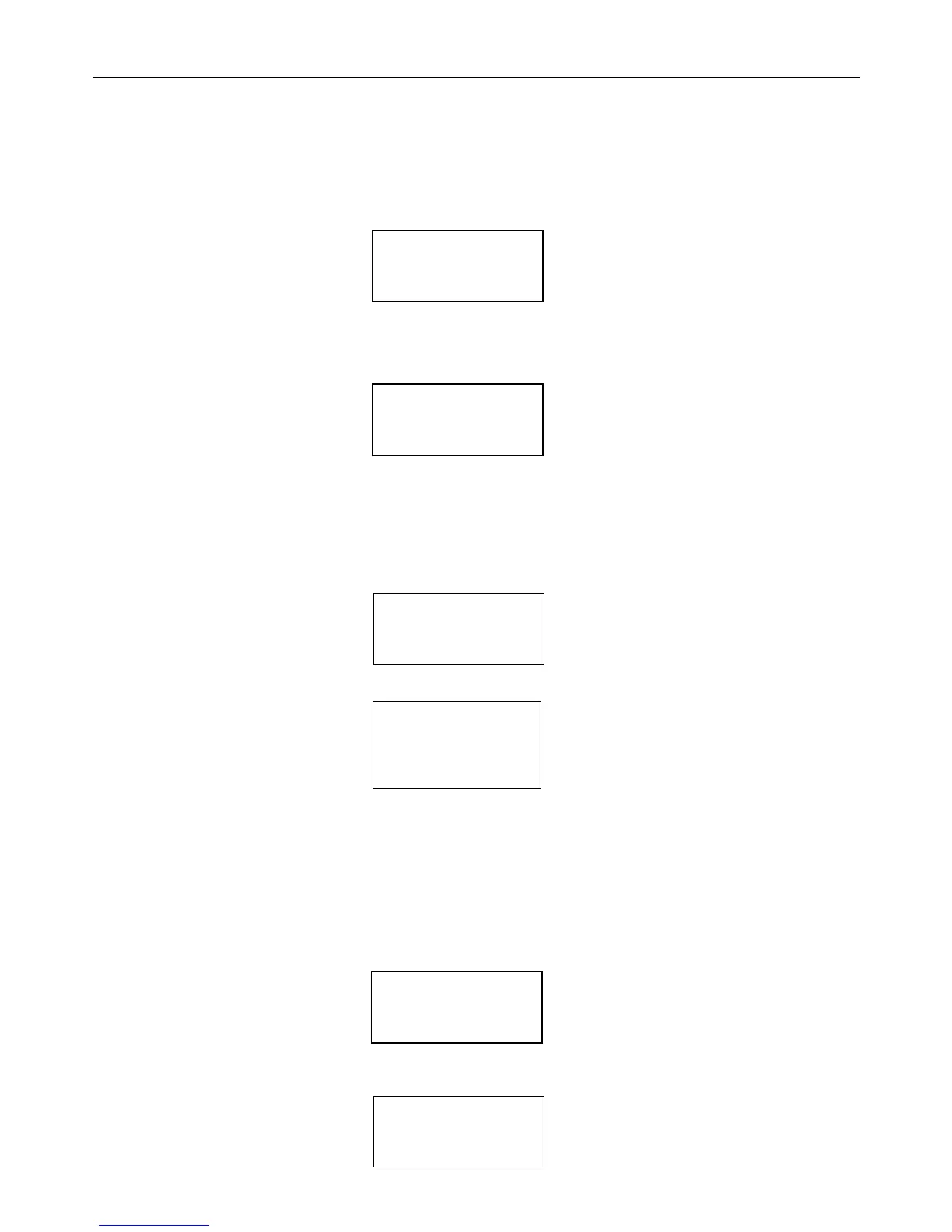
1) Press ENTER again: the configuration screen will be displayed, similar to the one below.
P:01 Adr
Priv/Shared
Trm1 32 Sh
Trm2 02 Pr
Trm3 -- --
Fig. 5.
Fig. 5.Fig. 5.
Fig. 5.g
gg
g
Change the configuration of the terminals as required. The ENTER button is used to move the cursor from one field to another, while the UP and DOWN buttons
change the value of the current field. P:xx shows the address of the selected pCO board (in the example shown in the figure, this is board 1).
To exit the configuration procedure and save the data, select the “Ok?” field, set “Yes” and confirm by pressing ENTER.
During the configuration procedure, if the terminal remains inactive (no button is pressed) for more than 30 seconds, the pCO board automatically exits the procedure
without saving any changes.
Important:
Important:Important:
Important: the pGD* terminals cannot be configured as “Sp” (shared with printer) as they do not have the printer output. Selecting this mode has no effect on the
management of the printed messages.
If during operation the terminal detects the inactivity of the pCO board whose output it is displaying, it cancels the display completely and then shows a message
similar to one below.
I/O board 01 fault
Fig. 5.
Fig. 5.Fig. 5.
Fig. 5.h
hh
h
If the terminal detects the inactivity of the entire pLAN network, that is, it does not receive any message from the network for 10 consecutive seconds, it cancels the
display completely and shows the following message:
 Loading...


