pCO Sistema
Code: +030220336 - rel. 1.5 - 22/12/10
36
4.4 Connecting the digital inputs
The pCO features digital inputs for connection to safety devices, alarms, device status indictors and remote control signals. These inputs are all optically-isolated from
the other terminals and can operate at 24 Vac, 24 Vdc and some at 230 Vac.
Note:
Note: Note:
Note: separate as much as possible the probe and digital input signal cables from the cables carrying inductive loads and power cables to avoid possible
electromagnetic disturbance.
IMPORTANT WARNINGS:
IMPORTANT WARNINGS: IMPORTANT WARNINGS:
IMPORTANT WARNINGS: if the control voltage is taken in parallel from a battery, install a dedicated RC filter in parallel with the battery (the typical features are 100
Ω, 0.5 µF, 630 V).
If connecting the digital inputs to safety systems (alarms), remember that
remember thatremember that
remember that: voltage across the contact must be considered as the normal operating condition, while no
voltage must represent an alarm situation. In this way, any interruption (or disconnection) of the input will also be signalled. Do not connect the neutral to an open
digital input. Always make sure that it is the line that is disconnected. The 24 Vac/Vdc digital inputs have a resistance of around 5 kΩ.
4.4.1
4.4.14.4.1
4.4.1 24 Vac digital inputs
24 Vac digital inputs24 Vac digital inputs
24 Vac digital inputs
For pCO
For pCOFor pCO
For pCO
3
33
3
, pCO
, pCO, pCO
, pCO
1
11
1
and pCO
and pCOand pCO
and pCO
C
CC
C
: all inputs can be 24 Vac.
: all inputs can be 24 Vac.: all inputs can be 24 Vac.
: all inputs can be 24 Vac.
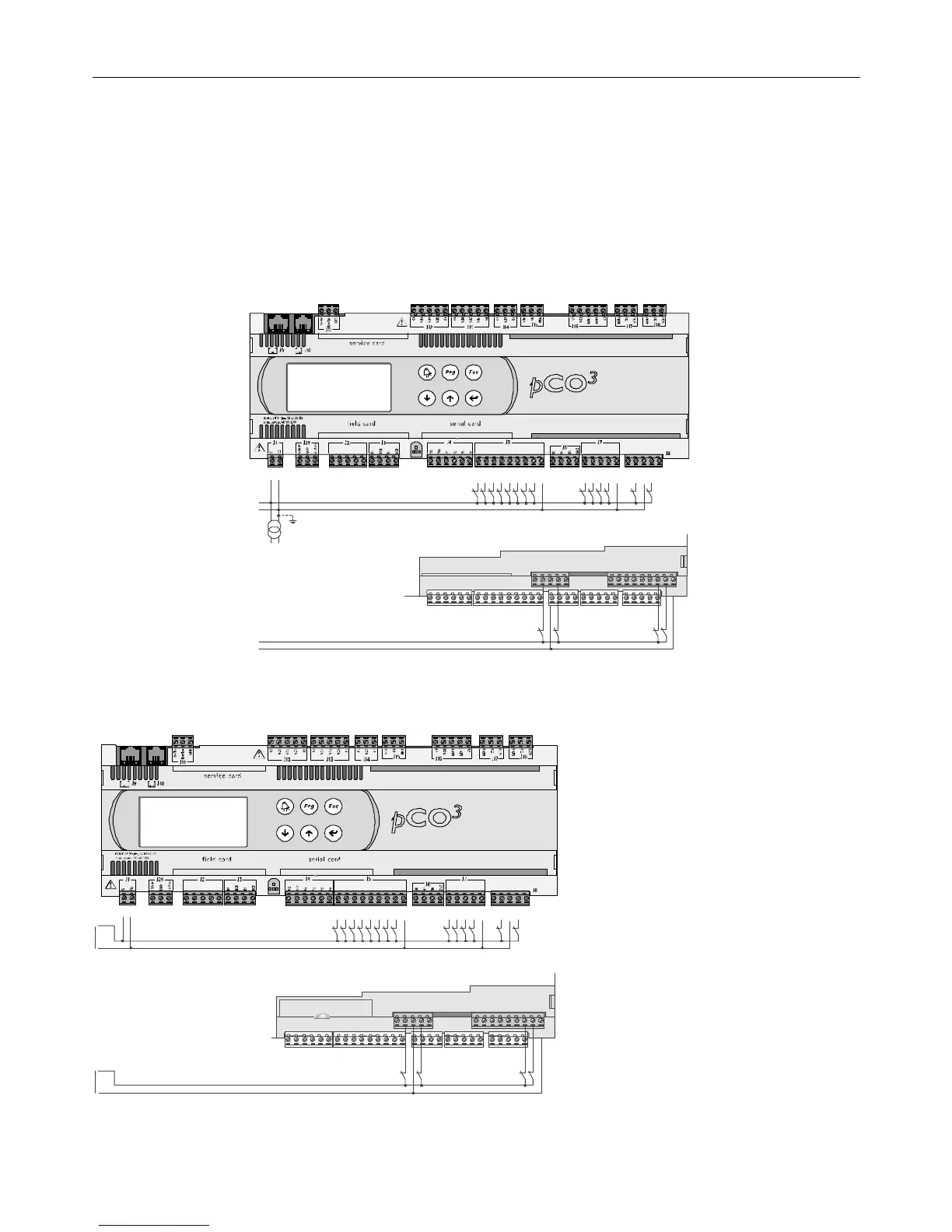
The following figure represents one of the most common diagrams for connecting the 24 Vac digital inputs, for a pCO
3
.
G
G0
24Vac
G
G0
ID1
ID2
ID3
ID4
ID5
ID6
ID7
ID8
IDC1
ID9
ID10
ID11
ID12
IDC9
ID13H
ID13
IDC13
ID14
ID14H
ID15H
ID15
IDC15
ID16
ID16H
Y5
Y6
ID17
ID18
IDC17
B9
BC9
B10
BC10
Serial Card
Fig. 4.h
Fig. 4.hFig. 4.h
Fig. 4.h
4.4.2
4.4.24.4.2
4.4.2 24 Vdc digital inputs
24 Vdc digital inputs24 Vdc digital inputs
24 Vdc digital inputs
For pCO
For pCOFor pCO
For pCO
3
33
3
, pCO
, pCO, pCO
, pCO
1
11
1
and pCO
and pCOand pCO
and pCO
C
CC
C
: all inputs can be 24Vdc.
: all inputs can be 24Vdc.: all inputs can be 24Vdc.
: all inputs can be 24Vdc.
The following figure represents one of the most common diagrams for connecting the 24 Vdc digital inputs, for a pCO
3
.
ID1
ID2
ID3
ID4
ID5
ID6
ID7
ID8
IDC1
ID9
ID10
ID11
ID12
IDC9
ID13H
ID13
IDC13
ID14
ID14H
ID15H
ID15
IDC15
ID16
ID16H
Y5
Y6
ID17
ID18
IDC17
B9
BC9
B10
BC10
Serial Card
24Vdc
+
-
24Vdc
+
-
Fig.4.i
Fig.4.iFig.4.i
Fig.4.i
To maintain the optical isolation of the digital inputs, a separate
power supply must be used just for the digital inputs; Figs. 4.h
and 4.i show the connection diagrams for the versions: MEDIUM
(extended) and LARGE (limited to the part regarding the
terminals located inside, on the board). While being the more
common and the simplest diagrams to complete, these do not
exclude the possibility of powering the digital inputs
independently from the power supply to the pCO.
In any case, the inputs only have functional insulation from the
rest of the controller.
Note:
Note:Note:
Note: there are no digital inputs in the Extra Large zone.
 Loading...


