Standard Shelter
Cod. +030221471 – Rel. 2.0 – April 01, 2003
14
10 MANUAL OPERATION OF THE DEVICES
The devices connected to the outputs can be activated manually, bypassing the safety times, the compressor rotation and independently of the
control functions and the values measured by the probes. The only support in manual mode involves the alarms, so as to ensure safety and
protect the devices. The activation of the analogue outputs in manual mode sets a value between 0V and 10V. The manual procedure can only
be used if the unit has been switched off using the button, and ends automatically 30 minutes after the manual activation of the last device.
During the manual operation of the devices, the shelter cannot be switched on. This operating mode is identified by the message “Manual
procedure” on the last row of the display, on the main Menu screen. The parameters for the manual operation of the devices are accessed in the
Maintenance branch of screens, with password protection.
11 AUTOMATIC ROTATION BETWEEN DIFFERENT SHELTER UNITS IN A pLAN
The boards connected in a pLAN network have the advantage of being able to be managed directly by the program in certain “critical
situations”, that is, if anomalies occur (alarms, blackouts…), or alternatively due to the “Rotation” and “Forcing” functions.
The program operates as defined by a number of parameters:
• connection class of the boards: Not present, Present / No Rotation, Present / Rotation. This parameter must be set on each master board. Description:
- Not present: the unit is not connected to the pLAN network;
- Present / No Rotation: the unit is physically connected to the pLAN network but is excluded from the rotation function (it can in any case
manage the unit in standby, the shared terminal and the print function);
- Present / Rotation: the unit also takes part in the Rotation function.
• Unit in Standby: In a pLAN network, one of the units in Present / Rotation mode may be in standby. When started using the button, this
unit enters Standby mode (that is, off, awaiting activation). Clearly, if there is only one unit in the network, this cannot be in standby.
IMPORTANT. The functions described below are not possible unless:
• There are at least two units selected in Present / Rotation mode
• One unit is in Standby
The functions are managed by the board with pLAN address 1; if this is disconnected from the pLAN network or is switched off due to a
blackout, the board in Standby is activated and the functions in question will be suspended until unit 1 is reset. Conversely, switching unit 1 off
using the On-off button does not interrupt the network functions.
11.1 CRITICAL SITUATIONS
The unit in Present / Rotation mode that is in Standby is activated in one of the following critical situations on the active boards:
• one of the boards is disconnected from the pLAN network
• one of the boards is switched off using the button
• one of the boards is switched off due to a serious alarm (see the alarm table)
When one of the units in critical situation is reset, this is started again and the spare unit returns to Standby mode.
If a critical situation occurs on the Standby unit, there is no action at a pLAN level, except for the alarm signal on the unit in question.
11.2 FORCING
The unit in Present / Rotation mode that is in Standby is activated automatically in the event where one of the other units cannot manage to
satisfy the heating or cooling request. Therefore, if the temperature increases such as to cause an excessive load on the active units, after a
certain time the required number of units in standby will be activated. Each unit in this situation can bring about the activation of the units in
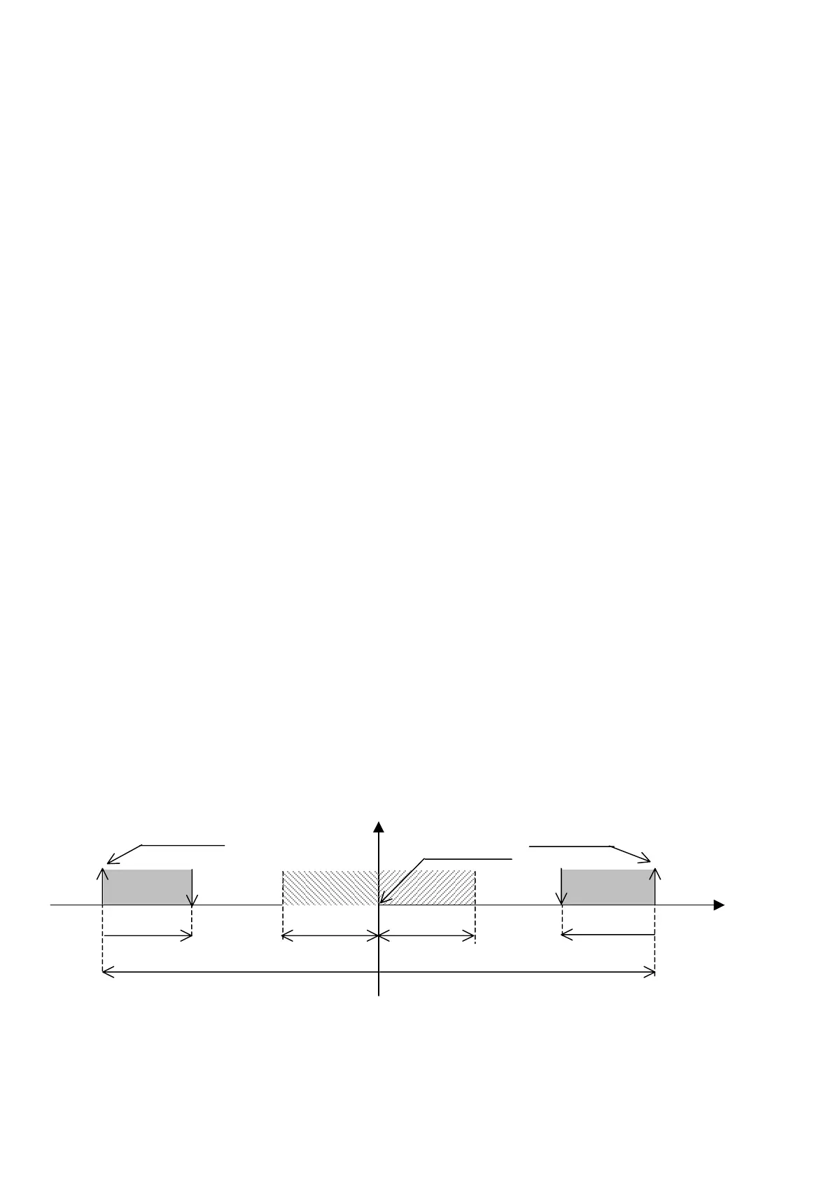
standby. The parameters that need to be set for the forcing function are the Differential, Offset and Delay, which are different for heating and
cooling. The diagram below illustrates the function:
NB.: All the values in the following graph refer to the default values
11.3 FIXED TIME ROTATION
Fixed time rotation is based on a parameter that establishes the interval between rotations. The minimum time that can be set is 0h, and in this case
automatic rotation is activated every each 5 minutes. The maximum time is 240h (10 days). The time starts counting when the board with pLAN address
1 is started, and indeed this board manages the rotation functions. Rotation occurs following the order of pLAN addresses.
Rotation will be reset automatically whenever a unit is added to or removed from the rotation function by modifying the connection class (see above).
15.0
Ambient
tem
.
°C
Set tem
erature
Heat band
Heating forcing differential
3°C
°
Offset in heating
°
Offset in cooling
Forcing delay in
heating
Forcing delay in
cooling
8.0ºC
8.0ºC
3°C
Cool band
19.0
16.5
23.0
26.5
27.0 31.0
Cooling forcing differential
 Loading...


