Standard Shelter
Cod. +030221471 – Rel. 2.0 – April 01, 2003
27
16 SUPERVISION
The pCO1 and pCO2 can be connected to a local or remote supervisor PC, via a GSM or analogue modem, as well as to the more commonly-used
BMS (Modbus, Bacnet, Lonworks). The use of the functions listed requires the installation of specific optional cards (RS485, RS232, LON) or
Gateways (devices that convert the different communication protocols).
16.1 CAREL SUPERVISOR
The local connection between the pCO1– pCO2 board and a supervisor PC requires the installation of the additional RS485 card (pCO2:
PCOSER48500; pCO1: PCO1004850) in the “Serial card” slot. The 3-wire RS485 line is then made from the screw connector on the additional card
to the RS485/RS232 converter supplied by Carel (PC485KIT00) for connection to the PC.
For a remote connection to the supervisor PC by phone line, simply fit the optional RS232 card (pCO2: PCO200MDM0; pCO1: PCO100MDM0)
and connect it to a standard modem (not GSM). The program manages the modem and allows the desired phone numbers to be set. For the
connections refer to the instruction sheets.
16.2 BMS
There are various different connections to the BMS supervisor systems.
Lonworks: fit the additional card in the “Serial card” slot (pCO2: PCO20LFTTL / PCO20L485L; pCO1: PCO10LFTTL / PCO10L485L) and make
the connections, referring to the instruction sheets. On the LCD terminal enable the LON function.
Modbus: fit the additional RS485 card; no other steps are required as the program automatically manages this protocol.
Bacnet: fit the additional RS485 card and connect it by an RS485 cable to the Carel gateway, code GATEWAYBN0.
Proprietary BMS: Carel has developed many other Gateways for interfacing to less common BMS, such as OTE.
16.3 GSM PROTOCOL
Selecting the GSM protocol allows SMS (text) messages to be sent to and received from GSM telephones, using a GSM modem. The pCO1 or pCO2
send messages to the telephone in the event of alarms, and can receive messages from the telephone at any time; in fact, with a GSM telephone the
user can modify the parameters listed below (for more information, refer to the Carel GSM modem protocol manual, code +030220330):
16.4 GSM VARIABLE DATABASE
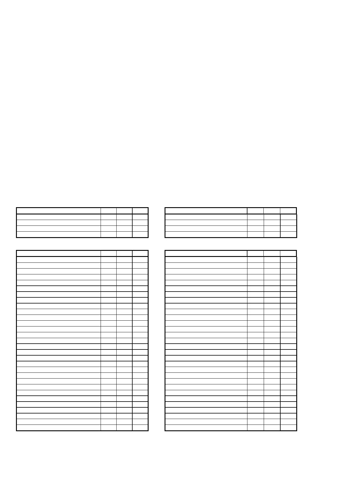
16.4.1 DIGITAL VARIABLES
DESCRIPTION SCR ADD. TYPE DESCRIPTION SCR ADD. TYPE
On/Off unit pLAN address1 -- 1 R/W On/Off unit pLAN address5
--
5 R/W
On/Off unit pLAN address2 -- 2 R/W On/Off unit pLAN address6
--
6 R/W
On/Off unit pLAN address3 -- 3 R/W On/Off unit pLAN address7
--
7 R/W
On/Off unit pLAN address4 -- 4 R/W On/Off unit pLAN address8
--
8 R/W
16.4.2 ANALOGUE VARIABLES
DESCRIPTION SCR ADD. TYPE DESCRIPTION SCR ADD. TYPE
Temperature set point U1 S0 1 R/W Low room temp. alarm offset U5 P8 31 R/W
Humidity set point U1 S0 2 R/W High room temp. alarm offset U5 P8 32 R/W
Low room temp. alarm offset U1 P8 3 R/W Low room humidity alarm offset U5 P9 33 R/W
High room temp. alarm offset U1 P8 4 R/W High room humidity alarm offset U5 P9 34 R/W
Low room humidity alarm offset U1 P9 5 R/W Outlet air set point limit U5 Pa 35 R/W
High room humidity alarm offset U1 P9 6 R/W Temperature set point U6 S0 36 R/W
Outlet air set point limit U1 Pa 7 R/W Humidity set point U6 S0 37 R/W
Temperature set point U2 S0 8 R/W Low room temp. alarm offset U6 P8 38 R/W
Humidity set point U2 S0 9 R/W High room temp. alarm offset U6 P8 39 R/W
Low room temp. alarm offset U2 P8 10 R/W Low room humidity alarm offset U6 P9 40 R/W
High room temp. alarm offset U2 P8 11 R/W High room humidity alarm offset U6 P9 41 R/W
Low room humidity alarm offset U2 P9 12 R/W Outlet air set point limit U6 Pa 42 R/W
High room humidity alarm offset U2 P9 13 R/W Temperature set point U7 S0 43 R/W
Outlet air set point limit U2 Pa 14 R/W Humidity set point U7 S0 44 R/W
Temperature set point U3 S0 15 R/W Low room temp. alarm offset U7 P8 45 R/W
Humidity set point U3 S0 16 R/W High room temp. alarm offset U7 P8 46 R/W
Low room temp. alarm offset U3 P8 17 R/W Low room humidity alarm offset U7 P9 47 R/W
High room temp. alarm offset U3 P8 18 R/W High room humidity alarm offset U74 P9 48 R/W
Low room humidity alarm offset U3 P9 19 R/W Outlet air set point limit U7 Pa 49 R/W
High room humidity alarm offset U3 P9 20 R/W Temperature set point U8 S0 50 R/W
Outlet air set point limit U3 Pa 21 R/W Humidity set point U8 S0 51 R/W
Temperature set point U4 S0 22 R/W Low room temp. alarm offset U8 P8 52 R/W
Humidity set point U4 S0 23 R/W High room temp. alarm offset U8 P8 53 R/W
Low room temp. alarm offset U4 P8 24 R/W Low room humidity alarm offset U8 P9 54 R/W
High room temp. alarm offset U4 P8 25 R/W High room humidity alarm offset U8 P9 55 R/W
Low room humidity alarm offset U4 P9 26 R/W Outlet air set point limit U8 Pa 56 R/W
High room humidity alarm offset U4 P9 27 R/W
Outlet air set point limit U4 Pa 28 R/W
Temperature set point U5 S0 29 R/W
Humidity set point U5 S0 30 R/W
For the syntax of the SMS messages sent to the pCO* and further information on the above table, refer to the manual: GSM modem protocol for
pCO2 (code+030220330).
N.B. When the GSM protocol is active, the remote supervisor cannot call the pCO1 or pCO2 board.
 Loading...


