Standard Shelter
Cod. +030221471 – Rel. 2.0 – April 01, 2003
28
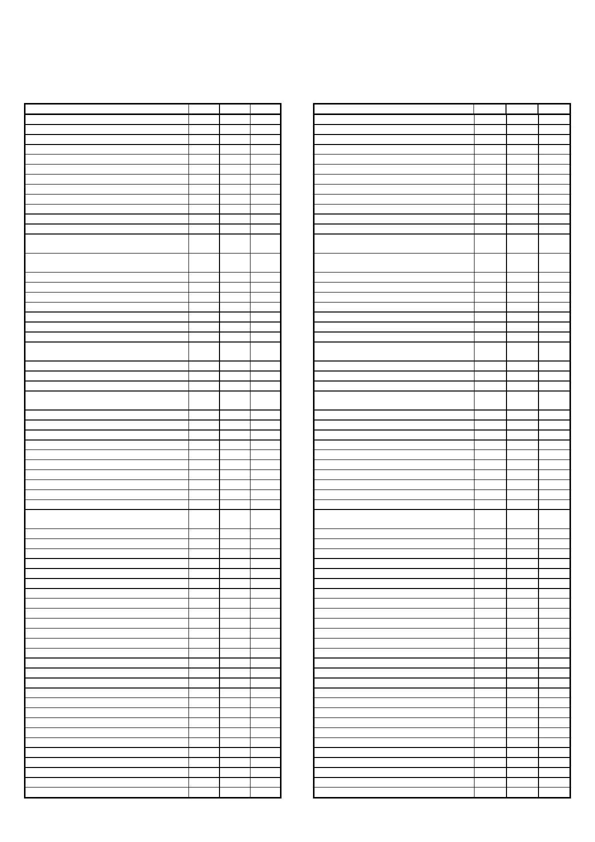
16.5 SUPERVISOR VARIABLE DATABASE
A specific communication database is featured that includes all the more important program variables, from the values read by the probes to the
parameters set on the screens. The following table describes the database, divided into digital, integer and analogue variables, indicating for each its
description, address and type, that is, read-only (R) or modifiable from the supervisor (R/W).
16.5.1 DIGITAL VARIABLES
DESCRIPTION SCR. ADD. TYPE DESCRIPTION SCR. ADD. TYPE
Digital input number 1 I3 1 R Driver 2 alarm, battery discharged or faulty
AL45
68 R
Digital input number 2 I3 2 R Driver 2 high evaporation press. (MOP)
AL46
69 R
Digital input number 3 I3 3 R Driver 2 low evaporation press. (LOP)
AL47
70 R
Digital input number 4 I4 4 R Driver 2 low superheating
AL48
71 R
Digital input number 5 I4 5 R Driver 2 high suction pressure
AL49
72 R
Digital input number 6 I4 6 R Driver 2 valve not closed during blackout
AL50
73 R
Digital input number 7 I5 7 R Cooling mode M1 74 R
Digital input number 8 I5 8 R Heating mode M1 75 R
Digital input number 9 I6 9 R Humidification mode M1 76 R
Digital input number 10 I6 10 R Dehumidification mode M1 77 R
Digital input number 11 I6 11 R Cooling limit M2 78 R
Digital input number 12 I7 12 R Dehumidification limit M2 79 R
Digital output number 1 Ia 13 R Type of condenser probe, circuit 1 (0=Pressure;
1=Temperature)
C7 80 R/W
Digital output number 2 Ia 14 R Type of condenser probe, circuit 2 (0=Pressure;
1=Temperature)
C8 81 R/W
Digital output number 3 Ia 15 R Enable pressure probe 1 C9 82 R/W
Digital output number 4 Ib 16 R Enable pressure probe 2 Ca 83 R/W
Digital output number 5 Ib 17 R Enable condenser 1 temp. probe Cb 84 R/W
Digital output number 6 Ic 18 R Enable condenser 2 temp. probe Cb 85 R/W
Digital output number 7 Ic 19 R Enable humidity probe Cc 86 R/W
Digital output number 8 Ic 20 R Enable outlet probe Cd 87 R/W
Digital output number 9 Id 21 R Enable outside temperature probe Ce 88 R/W
Digital output number 10 Id 22 R Select temperature unit of measure
(0=Centigrade; 1=Fahrenheit)
C0 89 R/W
Digital output number 11 Id 23 R Enable clock card (pCO1) C0 90 R/W
Generic alarm compressor 1 AL01 24 R Enable printer C0 91 R/W
Generic alarm compressor 2 AL02 25 R Type of freecooling (0=0-10V; 1=3pos.) C1 92 R/W
Low pressure alarm compressor 1
AL03
26 R Enable simultaneous freecooling and
compressor operation
C1 93 R/W
Low pressure alarm compressor 2 AL04 27 R Enable dehumidification C2 94 R/W
Air flow alarm AL05 28 R Enable humidification C2 95 R/W
Fan thermal cutout alarm AL06 29 R Enable modulating outlet fan C4 96 R/W
Thermal cutout alarm heater 1 AL07 30 R Enable condenser function C5 97 R/W
Thermal cutout alarm heater 2 AL08 31 R Enable second cond. coil C5 98 R/W
Fire / smoke alarm AL09 32 R Enable compressor FIFO rotation G1 99 R/W
Dirty filter alarm AL10 33 R Type of temperature control (0=P; 1=P+I) G1 100 R/W
High ambient temperature alarm AL11 34 R Enable high press. Prevent function G9 101 R/W
Low ambient temperature alarm AL12 35 R Enable unit Forcing in pLAN Gc 102 R/W
High ambient humidity alarm AL13 36 R Enable freecooling humidity limit P6 103 R/W
Low ambient humidity alarm
AL14
37 R Display language screen when starting the
pCO2-pCO1
P7
104 R/W
Op. hour threshold alarm, compressor 1 AL15 38 R Enable unit off from button P7 105 R/W
Op. hour threshold alarm, compressor 2 AL16 39 R Enable outlet limitation function Pa 106 R/W
Op. hour threshold alarm, fan AL17 40 R Unit On-Off from supervisor -- 107 R/W
Room temperature probe faulty alarm AL18 41 R Confirm hour setting -- 108 R/W
Outside temperature probe faulty alarm AL19 42 R Confirm minute setting -- 109 R/W
Outlet temperature probe faulty alarm AL20 43 R Confirm day setting -- 110 R/W
Room humidity probe faulty alarm AL21 44 R Confirm month setting -- 111 R/W
Pressure probe 1 faulty alarm AL22 45 R Confirm year setting -- 112 R/W
Pressure probe 2 faulty alarm AL23 46 R Confirm weekday setting -- 113 R/W
Cond. temp. probe 1 faulty alarm AL24 47 R Reset alarms from supervisor -- 114 R/W
Cond. temp. probe 2 faulty alarm AL25 48 R Driver 1 pLAN alarm AL51 115 R
Blackout alarm AL26 49 R Driver 2 pLAN alarm AL52 116 R
Clock card fault alarm AL27 50 R
High pressure alarm circuit 1 AL28 51 R
High pressure alarm circuit 2 AL29 52 R
Auxiliary alarm AL30 53 R
Op. hour threshold alarm, humidifier
AL31
54 R
pLAN alarm
AL32
55 R
Driver 1 alarm, probes faulty or disconnected
AL33
56 R
Driver 1 EEPROM faulty or damaged
AL34
57 R
Driver 1 valve motor faulty or damaged
AL35
58 R
Driver 1 alarm, battery discharged or faulty
AL36
59 R
Driver 1 high evaporation press. (MOP)
AL37
60 R
Driver 1 low evaporation press. (LOP)
AL38
61 R
Driver 1 low superheating
AL39
62 R
Driver 1 high suction pressure
AL40
63 R
Driver 1 valve not closed after blackout
AL41
64 R
 Loading...


